n
Wire Size and Torque Specifications
Select the appropriate wires and crimp terminals from
Table 3.10 . Crimp a ferrule to signal wiring to improve wiring simplicity and reliability. Refer
to Ferrule Terminal Types and Sizes on page 46.
Table 3.9 Wire Size and Torque Specifications (Same for All Models)
Terminal Screw Size
Tightening
Torque
N•m
Tightening Torque
(in-lbs)
Bare Wire Terminal Ferrule-Type Terminal
Wire Type
Applicable wire size
mm
2
(AWG)
Recomm. mm
2
(AWG)
Applicable wire size
mm
2
(AWG)
Recomm. mm
2
(AWG)
MA, MB, MC M3 0.5 to 0.6 4.4 to 5.3
Stranded: 0.25 to 1.5
(24 to 16)
Single: 0.25 to 1.5
(24 to 16)
0.75 (18)
0.25 to 1.0
(24 to 18)
0.5 (20)
Shielded line,
etc.
S1-S7, SC, RP, +V,
A1, A2, AC, HC, H1,
P1, P2, PC, MP, AM,
AC, S+, S-, R+, R-, IG
M2 0.22 to 0.25 1.9 to 2.2
Stranded: 0.25 to 1.0
(24 to 18)
Single: 0.25 to 1.5
(24 to 16)
0.75 (18)
0.25 to 0.5
(24 to 20)
0.5 (20)
n
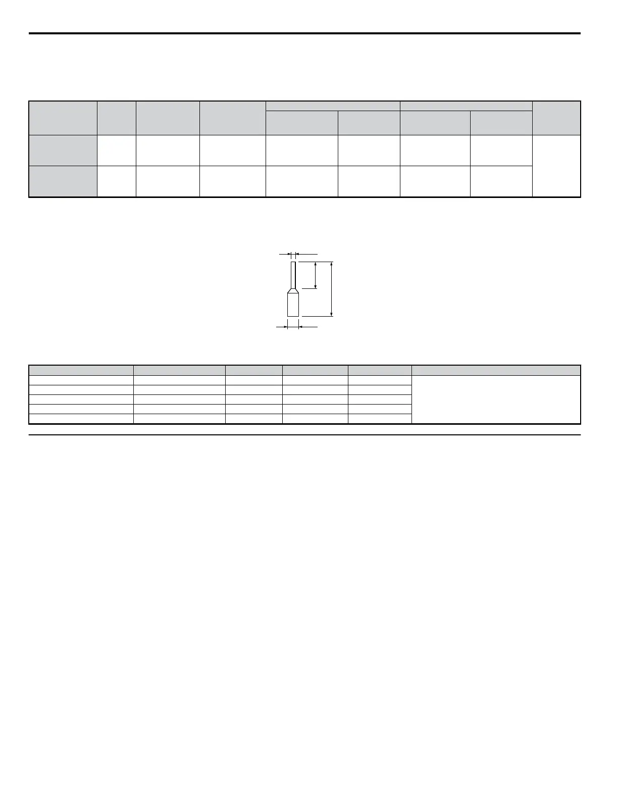
Ferrule-Type Wire Terminations
Crimp a ferrule to signal wiring to improve wiring simplicity and reliability. Use CRIMPFOX ZA-3, a crimping tool manufactured by PHOENIX
CONTACT.
fd1
fd2
6 mm
L
Figure 3.21 Ferrule Dimensions
Table 3.10 Ferrule Terminal Types and Sizes
Size mm
2
(AWG)
Type L (mm) d1 (mm) d2 (mm) Manufacturer
0.25 (24) AI 0.25-6YE 10.5 0.8 2
PHOENIX CONTACT
0.34 (22) AI 0.34-6TQ 10.5 0.8 2
0.5 (20) AI 0.5-6WH 12 1.1 2.5
0.75 (18) A1 0.75-6GY 12 1.3 2.8
1.0 AI 1-6RD 12 1.5 3.0
u
Wiring Procedure
This section describes the proper procedures and preparations for wiring the terminal board.
WARNING! Electrical Shock Hazard. Do not remove covers or touch the circuit boards while the power is on. Failure to comply could result in death or serious injury.
NOTICE: Separate control circuit wiring from main circuit wiring (terminals R/L1, S/L2, T/L3, B1, B2, U/T1, V/T2, W/T3, -, +1, +2) and other high-power lines. Improper wiring
practices could result in drive malfunction due to electrical interference.
NOTICE: Separate wiring for digital output terminals MA, MB and MC from wiring to other control circuit lines. Improper wiring practices could result in drive or equipment malfunction
or nuisance trips.
NOTICE: Use a class 2 power supply (UL standard) when connecting to the control terminals. Improper application of peripheral devices could result in drive performance degradation
due to improper power supply.
NOTICE: Insulate shields with tape or shrink tubing to prevent contact with other signal lines and equipment. Improper wiring practices could result in drive or equipment malfunction
due to short circuit.
NOTICE: Connect the shield of shielded cable to the appropriate ground terminal. Improper equipment grounding could result in drive or equipment malfunction or nuisance trips.
Wire the terminal board using Figure 3.22 as a guide (control circuit terminal block). Be sure to prepare the ends of the control circuit wiring as shown
in Figure 3.23 . Refer to Wire Gauges and Tightening Torque on page 41 for tightening torque specifications.
NOTICE: Do not tighten screws beyond the specified tightening torque. Failure to comply may damage the terminal block.
NOTICE: Use shielded twisted-pair cables as indicated to prevent operating faults. Improper wiring practices could result in drive or equipment malfunction due to electrical
interference.
3.7 Control Circuit Wiring
46
YASKAWA ELECTRIC SIEP C710606 18A YASKAWA AC Drive – V1000 Technical Manual (Preliminary)

 Loading...


