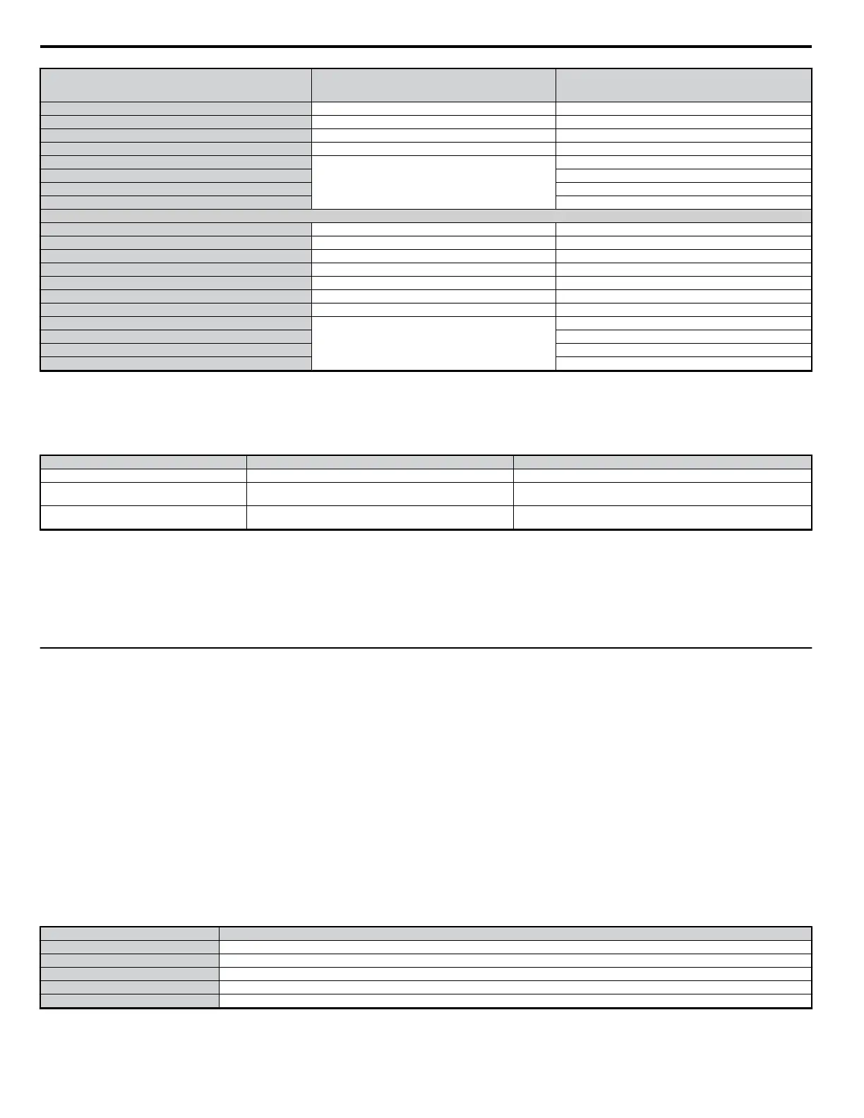
Drive Model CIMR-Vo
Time Delay/
Class RK5 Fuses
600 Vac, 200 kAIR
Fuse Ampere Rating
2A0006 TRS15R 15
2A0010 TRS25R 25
2A0012 TRS35R 35
2A0020 TRS60R 60
2A0030
Contact Yaskawa
70
2A0040 100
2A0056 150
2A0069 200
400 V Class Three-Phase Drives
4A0001 TRS2.5R 2.5
4A0002 TRS5R 5
4A0004 TRS10R 10
4A0005 TRS20R 20
4A0007 TRS20R 20
4A0009 TRS20R 20
4A0011 TRS30R 30
4A0018
Contact Yaskawa
50
4A0023 60
4A0031 70
4A0038 80
n
Low Voltage Wiring for Control Circuit Terminals
Wire low voltage wires with NEC Class 1 circuit conductors. Refer to national state or local codes for wiring. Use a class 2 (UL regulations) power supply
for the control circuit terminal.
Table D.6 Control Circuit Terminal Power Supply
Input / Output Terminal Signal Power Supply Specifications
Digital outputs P1*, P2*, PC*, MA, MB, MC, MP *Requires class 2 power supply.
Digital inputs S1, S2, S3, S4, S5, S6, S7, SC, H1, HC
Use the internal power supply of the drive. Use class 2 for external power
supply.
Main frequency reference (multi-function analog
inputs)
RP, +V, A1, A2, AC
Use the internal power supply of the drive. Use class 2 for external power
supply.
n
Drive Short-Circuit Rating
This drive has undergone the UL short-circuit test, which certifies that during a short circuit in the power supply the current flow will not rise above 30,000
amps maximum at 240 V for 200 V class drives and 480 V for 400 V class drives.
• The MCCB and breaker protection and fuse ratings shall be equal to or greater than the short-circuit tolerance of the power supply being used.
• Suitable for use on a circuit capable of delivering not more than 30,000 RMS symmetrical amperes for 240 V in 200 V class drives (up to 480 V for
400 V class drives) motor overload protection.
u
Drive Motor Overload Protection
Set parameter E2-01 (motor rated current) to the appropriate value to enable motor overload protection. The internal motor overload protection is UL
listed and in accordance with the NEC and CEC.
n
E2-01 Motor Rated Current
Setting Range: Model Dependent
Factory Default: Model Dependent
Parameter E2-01 (motor rated current) protects the motor if parameter L1-01 is not set to 0 (default is 1, standard induction motor protection enabled).
If Auto-Tuning has been performed successfully, the motor data that was entered in T1-04 is automatically written into parameter E2-01. If Auto-Tuning
has not been performed, manually enter the correct motor rated current in parameter E2-01.
n
L1-01 Motor Overload Protection Selection
The drive has an electronic overload protection function (OL1) based on time, output current and output frequency, which protects the motor from
overheating. The electronic thermal overload function is UL-recognized, so it does not require an external thermal overload relay for single motor operation.
This parameter selects the motor overload curve used according to the type of motor applied.
Table D.7 Overload Protection Settings
Setting Description
0 Disabled
1 Std Fan Cooled (< 10:1 motor) (factory default)
2 Standard Blower Cooled (10:1 motor)
3 Vector Motor (1000:1 motor)
4 PM motor
Disable the electronic overload protection (L1-01 = 0: Disabled) and wire each motor with its own motor thermal overload when connecting the drive to
more than one motor for simultaneous operation.
D.3 UL Standards
354
YASKAWA ELECTRIC SIEP C710606 18A YASKAWA AC Drive – V1000 Technical Manual (Preliminary)

 Loading...


