7.5 Drive Replacement
u
Serviceable Parts
The drive contains few serviceable parts. The following parts are considered replacement parts on the drive:
• Main control board and I/O Terminal board I/O PCBs.
• Cooling fan(s)
• Front cover
Replace the drive if the main power circuitry is damaged. Contact your local Yaskawa representative before replacing parts if the drive is still under
warranty. Yaskawa reserves the right to replace or repair the drive according to Yaskawa warranty policy.
WARNING! Electrical Shock Hazard. Do not connect or disconnect wiring while the power is on. Failure to comply can result in serious personal injury. Before servicing the drive,
disconnect all power to the equipment. The internal capacitor remains charged even after the power supply is turned off. The charge indicator LED will extinguish when the DC bus
voltage is below 50 Vdc. To prevent electric shock, wait at least five minutes after all indicators are OFF and measure the DC bus voltage level to confirm safe level.
u
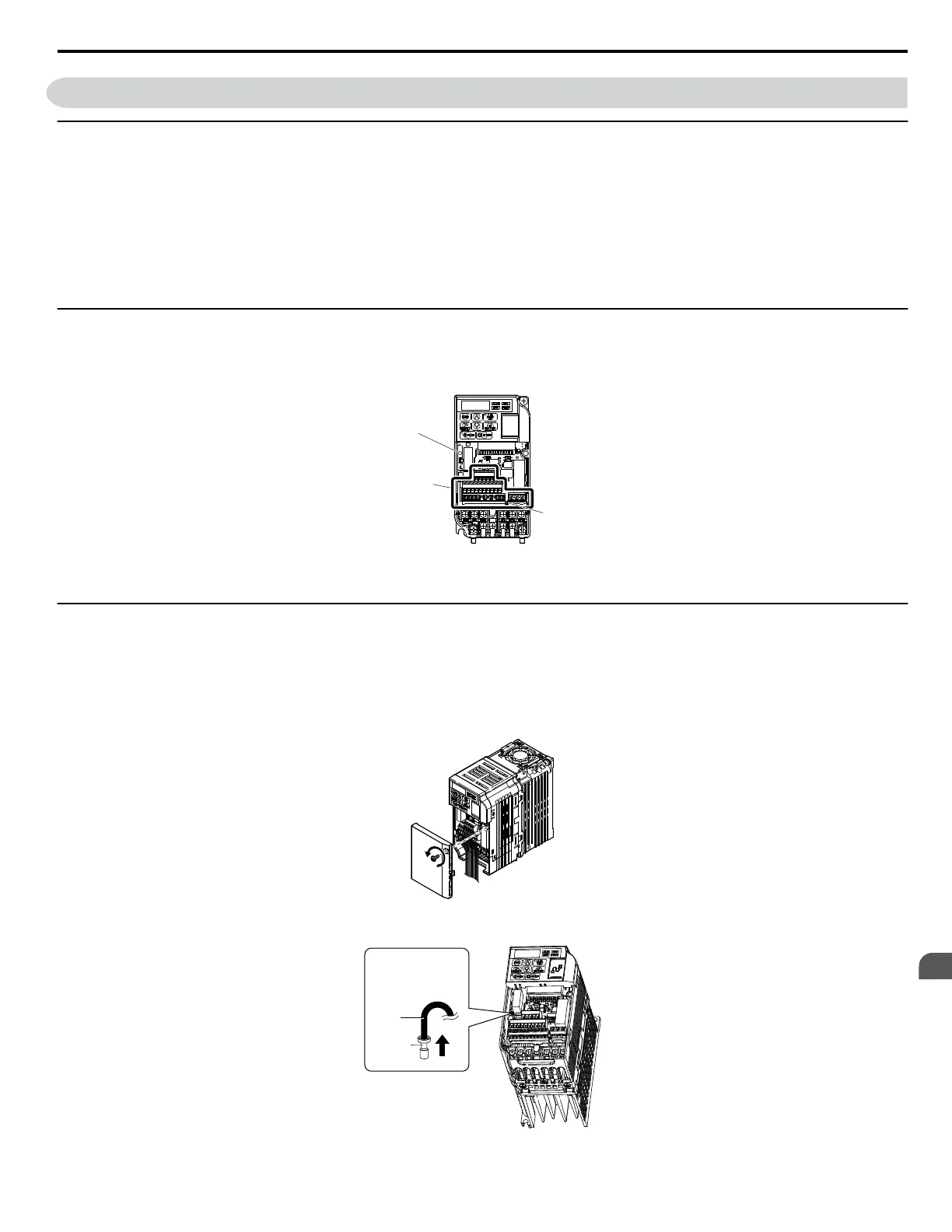
Terminal Board Overview
The drive has a modular I/O terminal block that facilitates quick drive replacement. The terminal board contains on-board memory that stores all drive
parameter settings and allows the parameters to be saved and transferred to the replacement drive by disconnecting the terminal board from the damaged
drive then reconnecting the terminal board to the replacement drive. There is no need to manually reprogram the replacement drive.
A
B
C
A – Charge LED
B – Terminal Board Screw
C – Removable Terminal Board
Figure 7.4 Terminal Board
u
Replacing the Drive
WARNING! Electrical Shock Hazard. Never connect or disconnect wiring, remove connectors or option cards, or replace the cooling fan while the power is on. Failure to comply
may result in serious injury. Before servicing, disconnect all power to the equipment. The internal capacitor remains charged even after the power supply is turned off.
WARNING! Electrical Shock Hazard. Do not allow unqualified personnel to perform work on the drive. Failure to comply could result in serious injury. Installation, maintenance,
inspection and servicing must be performed only by authorized personnel familiar with installation, adjustment and maintenance of AC drives.
NOTICE: Damage to Equipment. Observe proper electrostatic discharge procedures (ESD) when handling the drive and circuit boards. Failure to comply may result in ESD damage
to the drive circuitry.
1.
Loosen the screw on the front of the drive and remove the front cover.
Figure 7.5 Remove Front Cover
2.
Pull the pin on the ground terminal out of the removable terminal block.
Pull out the
ground terminal
pin in the direction
indicated by
the arrow.
Cable
Terminal
Figure 7.6 Depress Plastic Tab
7.5 Drive Replacement
YASKAWA ELECTRIC SIEP C710606 18A YASKAWA AC Drive – V1000 Technical Manual (Preliminary)
263
7
Periodic Inspection &
Maintenance

 Loading...


