Current Detection Speed Search looks for the speed of the motor by using the frequency when momentary power loss occured and by using the maximum
current. While searching for the speed, it adjusts the output frequency with the current the level, accelerating up to the specified frequency reference.
1: Speed Estimation Speed Search
Speed Estimation starts by first estimating the speed of the motor. Based on that speed, it adjust the frequency with the current level, accelerating up to
the specified frequency reference. Speed Estimation works both forwards and in reverse.
Note: For more informatin on Speed Search, Refer to b3-01: Speed Search Selection at Start on page 117.
n
b3-25: Speed Search Wait Time
Sets the wait time in units of 0.1 s bewteen Speed Search attempts when using a PM motor.
No. Parameter Name Setting Range Default Page
b3-25 Speed Search Wait Time 0.0 to 30.0 0.5 −
u
b4: Delay Timers
The drive has an internal timer function that operates independently from the drive. Delay times can function to get rid of chattering switch noise from
sensors.
n
b4-01: Timer Function On-Delay Time
n
b4-02: Timer Function Off-Delay Time
Sets the switching delay for the output in 0.1 s.
No. Parameter Name Setting Range Default
b4-01
*
Timer Function On-Delay Time 0.0 to 300.0 0.0
b4-02
*
Timer Function Off-Delay Time 0.0 to 300.0 0.0
Enabled when the timer function is set to one of the multi-function inputs (H1-oo) and multi-function outputs (H2-oo).
Detailed Description
A digital input must be programmed to be a timer start input by setting H1-oo = 18. A digital output must be programmed as a timer output by setting
H2-oo = 12. This should not to be confused with the “Wait to Run Time” in b1-11.
Multi-Function Inputs H1-01 through H1-07
Setting Function Name Page
18 Timer Function Input −
Multi-Function Outputs (H2-01 to H2-03)
Setting Function Name Page
12 Timer Function Output −
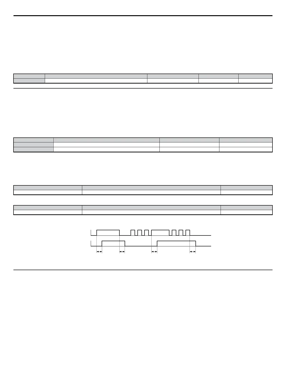
When the timer function input closes for longer than the value set in b4-01, the timer output switches on. When the timer function input is open for longer
than the value set in b4-02, the timer output function switches off. The following diagram demonstrates the timer function operation.
ON ON
ON ON
b4-01 b4-02 b4-01 b4-02
Multi-function Contact
Input: Timer Function
On (Closed)
Off (Open)
On (Closed)
Off (Open)
Multi-function Contact
Output: Timer Function
Figure 5.14 Timer Operation
u
b5: PID Control
The capability to accept an analog signal as feedback for a PID (Proportional + Integral + Derivative) control function is built into the drive. The PID
control function provides closed-loop control and regulation of a system variable such as temperature or pressure. A control signal based on the difference
(or proportion) between a feedback signal and a desired setpoint is produced. Integration and derivative calculations are then performed on this signal,
based upon the PID parameter settings (b5-01 to b5-19), to minimize deviation, for more precise control.
n
P Control
PID refers to the type of action used to control modulating equipment such as valves or dampers. With proportional control, a control signal based on the
difference between an actual condition and a desired condition is produced. The difference, such as that between an actual temperature and setpoint is the
“error”. The inverter adjusts its output signal related directly to the error magnitude.
n
I Control
The integral action is designed to minimize offset. An integrating term is used to observe how long the error condition has existed, summing the error
over time. Once the system has stabilized, the offset would be minimized.
5.2 b: Setup
122
YASKAWA ELECTRIC SIEP C710606 18A YASKAWA AC Drive – V1000 Technical Manual (Preliminary)

 Loading...


