n
C1-10: Accel/Decel Time Setting Units
Determines the units for the acceleration and deceleration times set to C1-01 through C1-09 using parameter C1-10. If any of the parameters C1-01 to
C1-09 are set to 600.1 seconds or more, then C1-10 cannot be set to 0.
No. Parameter Name Setting Range Default
C1-10 Accel/Decel Time Setting Units
0: Sets the accel/decel times in units of 0.01 s, making the setting range 0.00 to 600.00 s.
1: Sets the accel/decel times in units of 0.1 s, making the setting range 0.0 to 6000.0 s.
1
n
C1-11 Accel/Decel Switch Frequency
C1-11 allows the drive to switch automatically between the acceleration and deceleration times set to C1-01/C1-02 and C1-07/C1-08.
No. Parameter Name Setting Range Default
C1-11 Accel/Decel Switch Frequency 0.0 to 400.0 0.0 Hz
Detailed Description
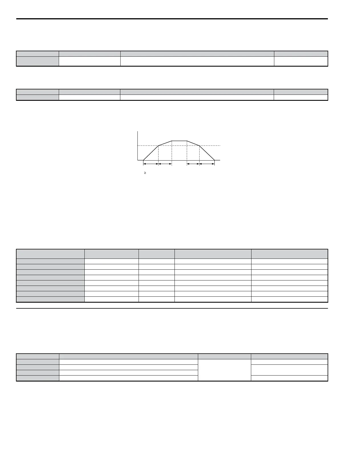
When the output frequency reaches the value set to C1-11, the drive will switch acceleration and deceleration times as shown in the graph below.
Note: Setting C1-11 to 0.0 Hz disables this function.
Output Frequency
C1-11
(Accel/Decel Time
Switch Frequency)
C1-07
When output frequency C1-11, the drive accelerates at Accel/Decel Time 1 (C1-01, -02)
When output frequency < C1-11, the drive accelerates at Accel/Decel Time 1 (C1-07, -08)
C1-01 C1-02 C1-08
Figure 5.21 Accel/Decel Time Switching Frequency
Acceleration time sets the time necessary for the output frequency to accelerate from 0Hz to maximum output frequency (E1-04). Deceleration time sets
the time necessary for the output frequency to decelerate from the maximum output frequency (E1-04) to 0 Hz.
C1-01 and C1-02 make up the default active accel/decel “pair”. Other accel/decel pairs (C1-03 to C1-08) exist that can be activated by a multi-function
digital input (H1-oo = 7 and 1A). Alternatively, the active accel/decel pair can be switched from first accel/decel pair (C1-01 and C1-02) to the fourth
accel/decel pair (C1-07 and C1-08) by a switch over frequency as programmed in parameter C1-11.
Motor 1 and 2 combinations with Accel/Decel Time 1 are shown in the table below. It is not possible to combine Accel/Decel Time 2 and motor switching
at the same time (this would trigger an oPE03 error, indicating a contradictory multi-function input settings).
Table 5.1 Motor Switching and Accel/Decel Time Combinations
Accel/Decel Time 1
(H1-oo = 7)
Output Frequency Status Motor 1 Selection Motor 2 Selection
Open C1-11 or above Accel C1-01 C1-05
Open C1-11 or above Decel C1-02 C1-06
Open less than C1-11 Accel C1-07 C1-07
Open less than C1-11 Decel C1-08 C1-08
Closed C1-11 or above Accel C1-03 C1-07
Closed C1-11 or above Decel C1-04 C1-08
Closed less than C1-11 Accel C1-03 C1-07
Closed less than C1-11 Decel C1-04 C1-08
u
C2: S-Curve Characteristics
Using S-curve characteristics to smooth acceleration and deceleration minimizes abrupt shock to the load. If a STo fault (Hunting Detection 2) occurs
when starting a PM motor, try increasing the value set to C2-01.
n
C2-01 to C2-04: S-Curve Characters
C2-01 through C2-04 set each part of the S-curve.
No. Parameter Name Setting Range Default
C2-01 S-Curve Characteristic at Accel Start
0.00 to 10.00 s
Determined by A1-02
C2-02 S-Curve Characteristic at Accel End
0.20 s
C2-03 S-Curve Characteristic at Decel Start
C2-04 S-Curve Characteristic at Decel End 0.00 s
The S-curve transition into and out of the active acceleration rate can be programmed independently.
5.3 C: Tuning
132
YASKAWA ELECTRIC SIEP C710606 18A YASKAWA AC Drive – V1000 Technical Manual (Preliminary)

 Loading...


