6.3 Drive Alarms, Faults, and Errors
u
Types of Alarms, Faults, and Errors
Check the LED operator for information about possible faults if the drive or motor fails to operate.
Refer to Using the Digital LED Operator on page
58.
If problems occur that are not covered in this manual, contact the nearest Yaskawa representative with the following information:
• Drive model
• Software version
• Date of purchase
• Description of the problem
Table 6.4 contains descriptions of the various types of alarms, faults, and errors that may occur while operating the drive.
Contact Yaskawa in the event of drive failure.
Table 6.4 Types of Alarms, Faults, and Errors
Type Drive Responses to Alarms, Faults, and Errors
Faults
When the drive detects a fault:
• The digital operator displays text that indicates the specific fault and the ALM indicator LED remains lit until the fault is reset.
• The fault interrupts drive output and the motor coasts to a stop.
• Depending on the setting, the drive and motor may stop via different methods than listed.
•
If a digital output is programmed for fault output (H2-oo = E), it will close if a fault occurs.
• When the drive detects a fault, it will remain inoperable until that fault has been reset.
Refer to Fault Reset Methods on page 247.
Minor Faults and Alarms
When the drive detects an alarm or a minor fault:
• The digital operator displays text that indicates the specific alarm or minor fault and the ALM indicator LED flashes.
• The motor does not stop.
•
One of the multi-function contact outputs closes if set to be tripped by a minor fault (H2-oo = 10), but not by an alarm.
• The digital operator displays text indicating a specific alarm and ALM indicator LED flashes.
• Remove the cause of an alarm or minor fault to automatically reset.
Operation Errors
When parameter settings conflict with one another or do not match hardware settings (such as with an option card), it results in an operation error.
When the drive detects an operation error:
• The digital operator displays text that indicates the specific error.
• Multi-function contact outputs do not operate.
• When the drive detects an operation error, it will not operate the motor until the error has been reset. Correct the settings that caused the operation error to reset.
Tuning Errors
Tuning errors occur while performing Auto-Tuning.
When the drive detects a tuning error:
• The digital operator displays text indicating the specific error.
• Multi-function contact outputs do not operate.
• Motor coasts to stop.
• Remove the cause of the error and repeat the Auto-Tuning process.
u
Alarm and Error Displays
n
Faults
When the drive detects a fault, the ALM indicator LEDs remain lit without flashing. If the LEDs flash, the drive has detected a minor fault or alarm.
Refer to Minor Faults and Alarms on page 227 for more information. An overvoltage situation trips both faults and minor faults, therefore it is important
to note whether the LEDs remain lit or if the LEDs flash.
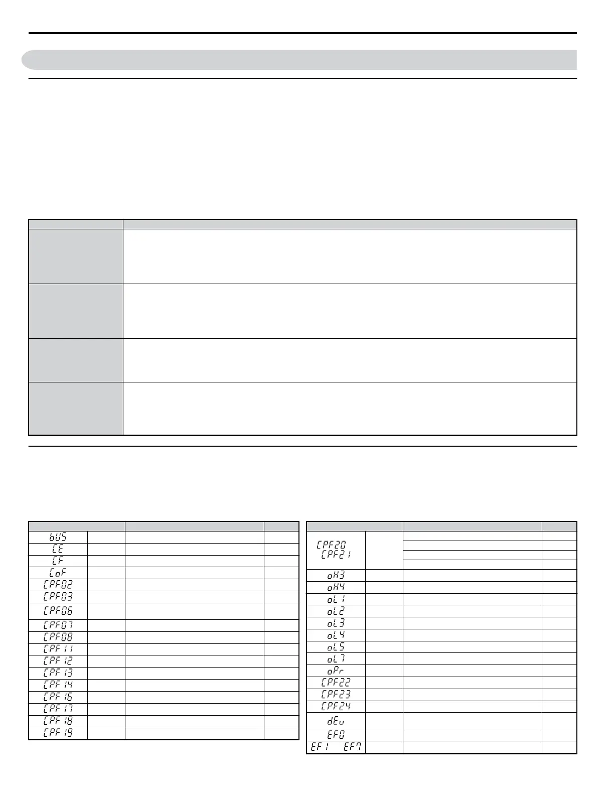
LED Operator Display Name Page
bUS Option Communication Error 229
CE MEMOBUS/Modbus Communication Error 229
CF Control Fault 229
CoF Current Offset Fault 229
CPF02 A/D Conversion Error 229
CPF03 PWM Data Fault 229
CPF06
Drive specification mismatch during Terminal
Board or Control Board replacement
229
CPF07 Terminal Board Communication Fault 230
CPF08 EEPROM Serial Communications Fault 230
CPF11 RAM Fault 230
CPF12 FLASH Memory Fault 230
CPF13 Watchdog Circuit Exception 230
CPF14 Control Circuit Fault 230
CPF16 Clock Fault 230
CPF17 Timing Fault 230
CPF18 Control Circuit Fault 230
CPF19 Control Circuit Fault 230
LED Operator Display Name Page
or CPF20or
CPF21
RAM Fault 230
FLASH Memory Fault 230
Watchdog Circuit Exception 230
Clock Fault 230
oH3 Motor Overheat 1 (PTC input) 233
oH4 Motor Overheat 2 (PTC input) 233
oL1 Motor Overload 234
oL2 Drive Overload 234
oL3 Overtorque Detection 1 234
oL4 Overtorque Detection 2 234
oL5 Mechanical Weakening Detection 1 234
oL7 High Slip Braking OL 235
oPr Operator Connection Fault 235
CPF22 A/D Conversion Error 230
CPF23 PWM Feedback Data Fault 230
CPF24 Drive Capacity Signal Fault 230
dEv
Excessive Speed Deviation(for Simple V/f with
PG)
231
EF0 Option Card External Fault 231
to
EF1 to EF7 External Fault (input terminal S1 to S7) 231
6.3 Drive Alarms, Faults, and Errors
226
YASKAWA ELECTRIC SIEP C710606 18A YASKAWA AC Drive – V1000 Technical Manual (Preliminary)

 Loading...


