Cause Possible Solution
Hardware is damaged. Replace the drive.
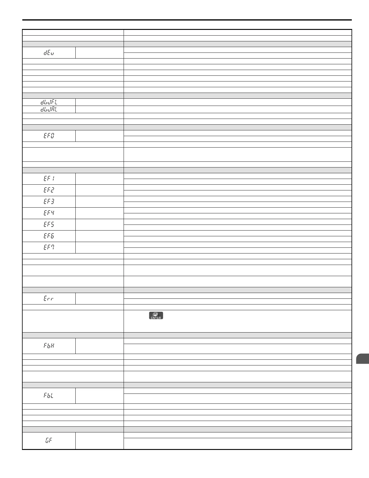
LED Operator Display Fault Name
dEv
Speed Deviation (for Simple V/f with PG)
According to the pulse input (RP), the speed deviation is greater than the setting in F1-10 for longer than the time set to F1-11.
Cause Possible Solution
Load is too heavy. Reduce the load.
Acceleration and deceleration times are set too short. Increase the acceleration and deceleration times (C1-01 through C1-08).
The load is locked up. Check the machine.
Parameters are not set appropriately. Check the settings of parameters F1-10 and F1-11.
Motor brake engaged. Ensure the motor brake releases properly.
LED Operator Display Fault Name
dWFL DriveWorksEZ Fault
dWAL DriveWorksEZ Program Error Output
Cause Possible Solution
DriveWorksEZ program output a fault. • Correct whatever caused the fault to occur.
LED Operator Display Fault Name
EF0
Option Card External Fault
An external fault condition is present.
Cause Possible Solution
An external fault was received from the PLC with F6-03 =
3 “alarm only” (the drive continued to run after external
fault).
• Remove the cause of the external fault.
• Remove the external fault input from the PLC.
Problem with the PLC program. Check the PLC program and correct problems.
LED Operator Display Fault Name
EF1
External Fault (input terminal S1)
External fault at multi-function input terminal S1.
EF2
External Fault (input terminal S2)
External fault at multi-function input terminal S2.
EF3
External Fault (input terminal S3)
External fault at multi-function input terminal S3.
EF4
External Fault (input terminal S4)
External fault at multi-function input terminal S4.
EF5
External Fault (input terminal S5)
External fault at multi-function input terminal S5.
EF6
External Fault (input terminal S6)
External fault at multi-function input terminal S6.
EF7
External Fault (input terminal S7)
External fault at multi-function input terminal S7.
Cause Possible Solution
An external device has tripped an alarm function. Remove the cause of the external fault and reset the fault.
Wiring is incorrect.
•
Ensure the signal lines have been connected properly to the terminals assigned for external fault detection (H1-oo = 20 to 2F).
• Reconnect the signal line.
Incorrect setting of multi-function contact inputs.
•
Check if the unused terminals set for H1-oo = 20 to 2F (External Fault).
• Change the terminal settings.
LED Operator Display Fault Name
Err
EEPROM Write Error
Data does not match the EEPROM being written to.
Cause Possible Solution
-
•
Press the button.
• Correct the parameter settings.
• Cycle power to the drive. Refer to Diagnosing and Resetting Faults on page 247.
LED Operator Display Fault Name
FbH
Excessive PID Feedback
PID feedback input is greater than the level set b5-36 for longer than the time set to b5-37. To enable fault detection, set b5-12 = “2” or
“5”.
Cause Possible Solution
Parameters are not set appropriately. Check the settings of parameters b5-36 and b5-37.
Wiring for PID feedback is incorrect. Correct the wiring.
There is a problem with the feedback sensor.
• Check the sensor on the control side.
• Replace the sensor if damaged.
LED Operator Display Fault Name
FbL
PID Feedback Loss
This fault occurs when PID Feedback Loss Detection is programmed to fault (b5-12 = 2) and the PID Feedback < PID Feedback Loss
Detection Level (b5-13) for the PID Feedback Loss Detection Time (b5-14).
Cause Possible Solution
Parameters are not set appropriately. Check the settings of parameters b5-13 and b5-14.
Wiring for PID feedback is incorrect. Correct the wiring.
There is a problem with the feedback sensor. Check the sensor on the controller side.If damaged, replace the sensor.
LED Operator Display Fault Name
GF
Ground Fault
• Current shorted to ground exceeded 50% of rated current on output side of the drive.
• Setting L8-09 to 1 enables ground fault detection in models 5.5 kW or larger.
6.4 Fault Detection
YASKAWA ELECTRIC SIEP C710606 18A YASKAWA AC Drive – V1000 Technical Manual (Preliminary)
231
6
Troubleshooting

 Loading...


