n
Basic Auto-Tuning Preparations
• Auto-Tuning automatically determines the electrical characteristics of the motor. This is fundamentally different from other types of Auto-Tuning
features used in servo systems.
• Before auto-tuning, be sure the input supply voltage equals or exceeds the motor rated voltage. Performance can be enhanced by using a motor with a
base voltage that is 20 V (40 V for 400 V class models) lower than the input supply voltage. This may be of special importance when operating the
motor above 90% of base speed, where high torque precision is required.
• Auto-Tuning is not possible with permanent magnet motors.
• To cancel Auto-Tuning, press the STOP key on the LED operator.
• The next table describes digital input and output terminal status during Auto-Tuning.
Auto-Tuning Type Digital Input Digital Output
Auto-Tuning for Energy Savings in V/f Control Not available Works the same during normal operation
Rotational-Type Auto-Tuning Not available Works the same during normal operation
Auto-Tuning for Resistance between Lines Not available Maintains the status at the start of Auto-Tuning
WARNING! When Auto-Tuning a motor that is used on an application in conjunction with a brake, take special precaution to insure the brake stays applied. Auto-Tuning activates
the drive multi-function outputs per the table below. Therefore, a brake may be released while the motor is uncoupled from the load, resulting in an unsafe condition. Proper
precautions must therefore be taken prior to performing Auto-Tuning.
Note: It is recommended that Rotational Auto-Tuning be performed with the load disconnected. Failure to comply could result in improper drive operation. If rotational Auto-Tuning
is performed for a motor coupled to a load, the motor constants will be inaccurate and the motor may exhibit abnormal operation. Disconnect or decouple the motor from the
load.
n
Rotational Auto-Tuning for V/f Control
• Motor rotates during Auto-Tuning.
• Sets parameters required for torque compensation, slip compensation, energy savings, and speed search.
• Available only when the drive is set for V/f Control.
• Required to perform Estimation-Type Speed Search when using V/f Control.
n
Rotational Auto-Tuning for Open Loop Vector Control
• Used only when in Open Loop Vector Control.
• Perform only with the motor uncoupled from the load for applications requiring high performance over a wide speed range.
• Disconnect the load before Auto-Tuning the drive and motor. Performing Rotational Auto-Tuning with the load connected will set motor parameters
incorrectly, and also be dangerous because irregular motor rotation will occur.
• It is possible to perform Rotational Auto-Tuning with a connected load if the load is less than 30% of the rated load.
• Ensure a motor-mounted brake is fully released.
• Connected machinery should not produce enough power to rotate the motor.
n
Stationary Auto-Tuning for Terminal Resistance Only
• If the motor cable lead length has been significantly modified after Auto-Tuning has already been performed, perform Stationary Auto-Tuning with
the new cables.
• Perform when using motor cables longer than 50 m with V/f Control.
WARNING! Electrical Shock Hazard. When executing stationary Auto-Tuning for line-to-line resistance only, the motor does not rotate, however, power is applied. Do not touch
the motor until Auto-Tuning is completed. Failure to comply may result in injury from electrical shock.
Note: When auto-tuning a motor that is used on an application in conjunction with a brake, take special precaution to ensure the brake stays applied.
u
Auto-Tuning Fault Codes
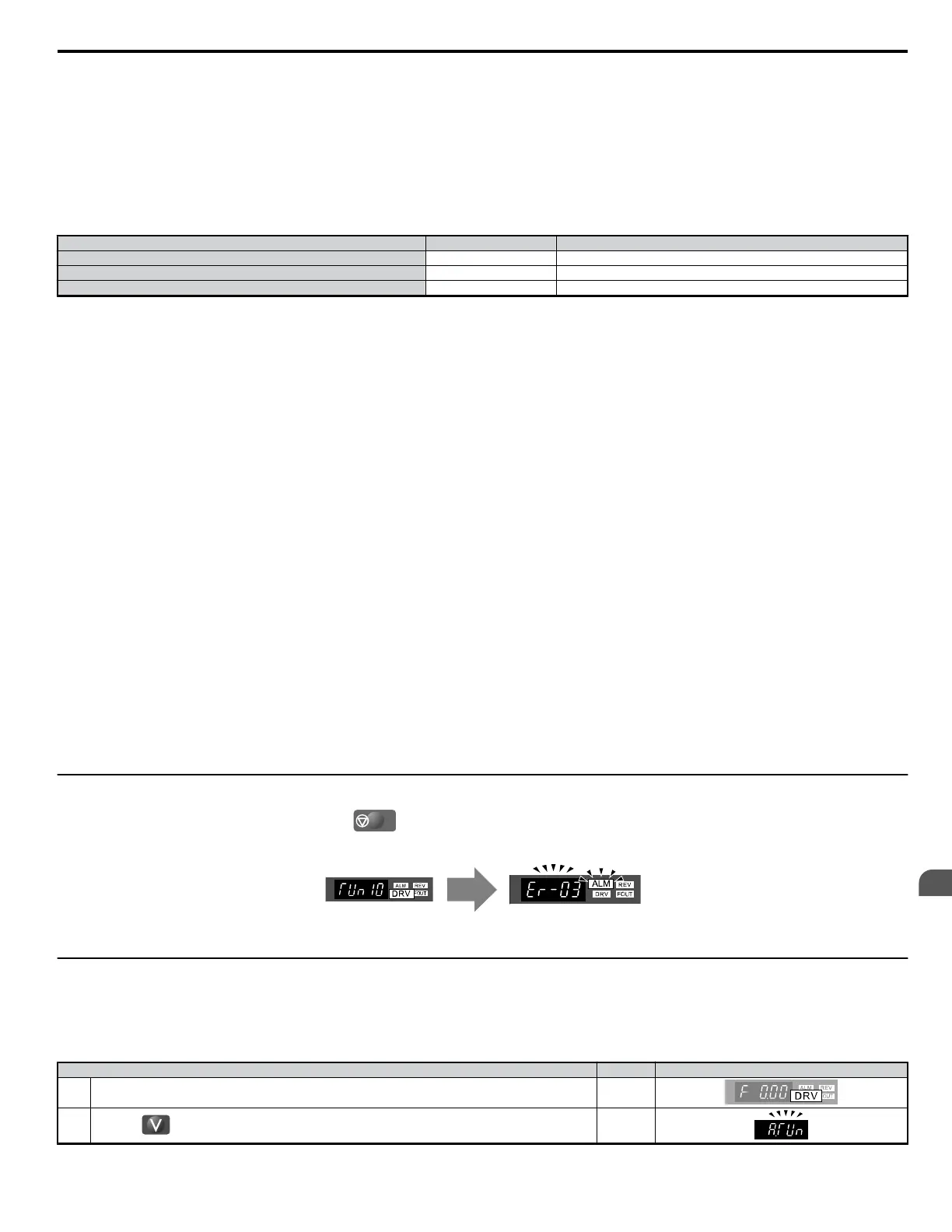
Calculation of abnormal measurements or pressing
STOP
before completion will interrupt Auto-Tuning.
A B
A – Normal Auto-Tuning Display B – Auto-Tuning Interrupted
Figure 5.76 Auto-Tuning Interruption Display
u
Performing Auto-Tuning
The following example illustrates how to perform Rotational Auto-Tuning.
Note: The following example is shown with the drive in Open Loop Vector Control (A1-02 = 2).
n
Selecting the Type of Auto-Tuning
Step Display/Result
1. Turn on the power to the drive. The initial display appears.
⇒
2.
Press the key until the Auto-Tuning screen appears.
⇒
5.11 Auto-Tuning
YASKAWA ELECTRIC SIEP C710606 18A YASKAWA AC Drive – V1000 Technical Manual (Preliminary)
211
5
Parameter Details

 Loading...


