1.4 Component Names
This section illustrates the drive components as they are mentioned in this manual.
Note:
Refer to Operation Instructions on page 95 for a detailed description of digital operator functions. The digital LED operator is not removable.
Note: The number of drive cooling fans varies depending on drive model.
u
IP20/Open-Chassis
n
Single-phase AC200 V CIMR-V
oBA0001B ~ 0003B
Three-phase AC200 V CIMR-Vo2A0001B ~ 0006B
A
B
C
D
E
F
G
H
I
J
L
K
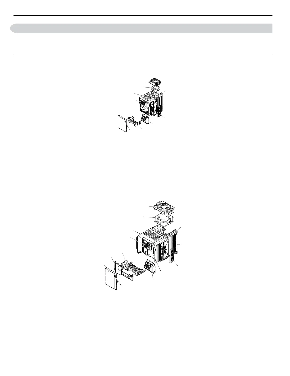
A – Fan cover
B – Mounting hole
C – Heatsink
D – Optional 24 V DC power supply
connector cover
E – Terminal board Refer to Control
Circuit Terminal Block Functions on
page 44
F – Terminal cover
G – Front cover screw
H – Front cover
I – Comm port
J – LED operator Refer to Using the
Digital LED Operator on page 58
K – Drive case
L – Cooling fan Refer to Drive Cooling
Fans on page 261
Figure 1.2 Exploded View of IP20/Open-Chassis Type Components
Three-Phase AC200 V CIMR-Vo2A0006B
n
Single-Phase AC200 V CIMR-V
oBA0006B ~ 0018B
Three-Phase AC200 V CIMR-Vo2A0010B ~ 0020B
Three-Phase AC400 V CIMR-Vo4A0001B ~ 0011B
A
B
C
D
E
F
G
H
I
J
M
K
L
A – Fan cover
B – Mounting hole
C – Heatsink
D – Optional 24 V DC power supply
connector cover
E – Comm port
F – Terminal board Refer to Control
Circuit Terminal Block Functions on
page 44
G – Front cover screw
H – Front cover
I – Terminal cover
J – Bottom cover
K – LED operator
Refer to Using the
Digital LED Operator on page 58
L – Case
M – Cooling fan Refer to Drive Cooling
Fans on page 261
Figure 1.3 Exploded view of IP20/Open-Chassis Type Components
Three-Phase AC200 V CIMR-Vo2A0012B
Note:
CIMR-VoBA0018B is supplied with two built-in cooling fans.
1.4 Component Names
20
YASKAWA ELECTRIC SIEP C710606 18A YASKAWA AC Drive – V1000 Technical Manual (Preliminary)

 Loading...


