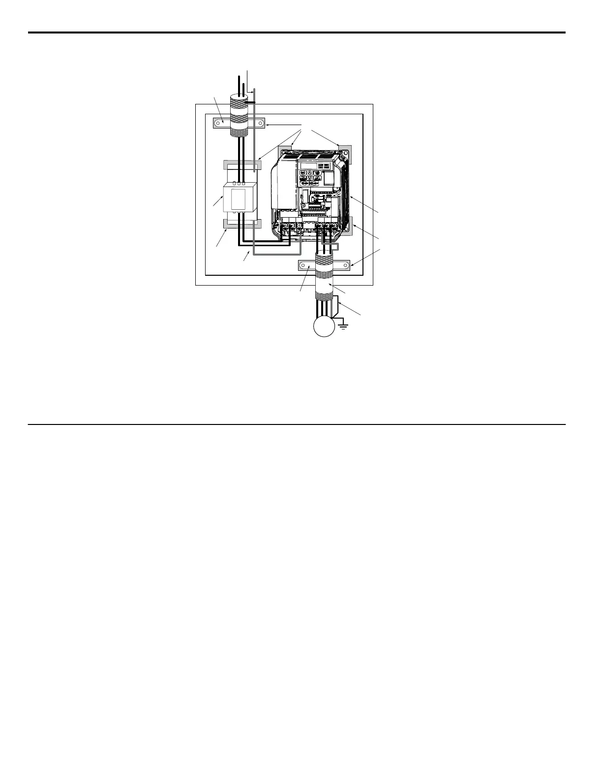
Single-Phase 200 V Class
L3 L2 L1L3 L2 L1
E
L2
L1
PE
R/L1 S/L2 T/L3
U/T1 V/T2
W/T3
C
D
H
H
D
D
I
E
J
B
F
G
A
A
A – Ground the cable shield
B – Enclosure panel
C – Metal plate
D – Grounding surface (remove any paint
or sealant)
E – Drive
F – Motor cable (braided shield cable,
max. 20 m)
G – Motor
H – Cable clamp
I – Max. distance between drive and
noise filter
J – EMC noise filter
Figure 8.14 EMC Filter and Drive Installation for CE Compliance
(Single-Phase 200 V Class)
u
Installing a Motor Thermal Overload (OL) Relay on the Drive Output
Motor thermal overload relays protect the motor by disconnecting power lines to the motor due to a motor overload condition.
Install a motor thermal overload relay between the drive and motor:
• When operating multiple motors on a single AC drive.
• When using a power line bypass to operate the motor directly from the power line.
It is not necessary to install a motor thermal overload relay when operating a single motor from a single AC drive. The AC drive has UL recognized
electronic motor overload protection built into the drive software.
Note: Disable the motor protection function (L1-0 1 = “0”) when using an external motor thermal overload relay. The relay should shut off main power on the input side of the main
circuit when triggered.
Special application precautions should be considered when using motor thermal overload relays on the output of AC drives. The following may occur if
a motor thermal OL relay is connected to the output of an AC drive (between the drive and the motor) when the carrier frequency is high and the wiring
between the motor and the drive is long:
• Thermal relay nuisance trips occur.
• The thermal relay may be damaged due to excessive heat loss.
Some considerations involving AC drives and use of thermal overload relays:
1. Low speed motor operation
2. Use of multiple motors on a single AC drive
3. Motor cable length greater than 50 meters (164 feet)
4. Voltage boost and high torque V/f pattern settings
5. Nuisance tripping resulting from high AC drive carrier frequency
n
General Precautions to Prevent Tripping of Motor Thermal Overload Relays
Low Speed Operation and Motor Thermal OL Relays
Generally, thermal relays are applied on general-purpose motors. When general-purpose motors are driven by AC drives, the motor current is approximately
5 ~ 10% greater than if driven by the commercial power supply. In addition, the cooling capacity of a motor with a shaft-driven fan decreases when
operating at low speeds. Even if the load current is within the motor rated value, motor overheating may occur. A thermal relay cannot effectively protect
the motor due to the reduction of cooling at low speeds. For this reason, apply the UL-recognized electronic thermal overload protection function built
into the drive whenever possible.
8.4 Installing Peripheral Devices
276
YASKAWA ELECTRIC SIEP C710606 18A YASKAWA AC Drive – V1000 Technical Manual (Preliminary)

 Loading...


