3.5 Protective Covers
Follow the procedure below to remove the protective covers before wiring the drive and to reattach the covers after wiring is complete.
u
IP20/Open-Chassis
n
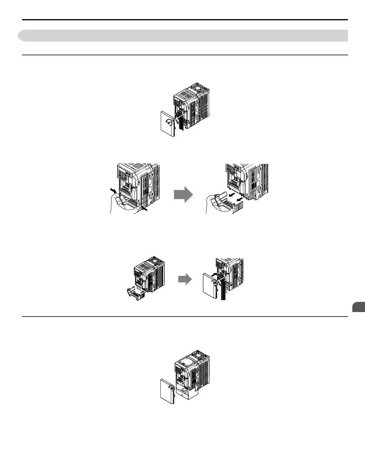
Removing the Protective Covers
1.
Loosen the screw that locks the front cover in place to remove.
Figure 3.10 Remove the Front Cover on an IP20/Open-Chassis Drive
2.
Apply pressure to the tabs on each side of the terminal cover. Pull the terminal cover away from the drive while pushing in on the tabs to pull the
cover free.
Figure 3.11 Remove the Terminal Cover on an IP20/Open-Chassis Drive
n
Reattaching the Protective Covers
Properly connect all wiring and route power wiring away from control signal wiring. Reattach all protective covers when wiring is complete. Apply only
a small amount of pressure to lock the cover back into place.
Figure 3.12 Reattach the Protective Covers on an IP20/Open-Chassis Drive
u
IP20/NEMA Type 1
n
Removing the Protective Covers on an IP20/NEMA Type 1 design
1.
Loosen the screw on the front cover to remove the front cover.
Figure 3.13 Remove the Front Cover on an IP20/NEMA Type 1 Drive
2.
Loosen the screw on the terminal cover (
Figure 3.14 , B) to remove the terminal cover and expose the conduit bracket ( Figure 3.14 , A).
3.5 Protective Covers
YASKAWA ELECTRIC SIEP C710606 18A YASKAWA AC Drive – V1000 Technical Manual (Preliminary)
39
3
Electrical Installation

 Loading...


