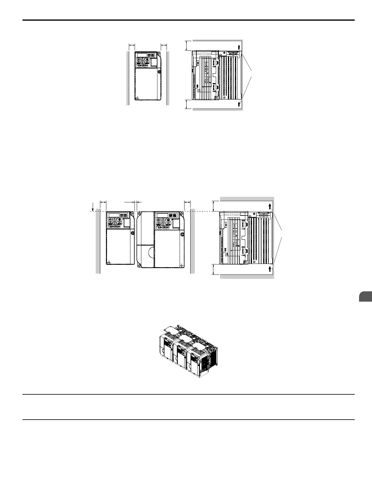
Side Clearance
A A
Top/Bottom Clearance
B
C
C
A – 30 mm minimum
B – Airflow direction
C – 100 mm minimum
Figure 2.2 Correct Installation Spacing
Note: IP20/NEMA Type 1 and IP20/Open-Chassis models require the same amount of space above and below the drive for installation.
n
Multiple Drive Installation
When installing multiple drives into the same enclosure panel, mount the drives according to
Figure 2.2 . When mounting drives with a minimum side-
by-side clearance of 2 mm according to Figure 2.3 , derating must be considered and parameter L8-35 must be set. Refer to Parameter List on page
293.
2 mm
A
B
B
C
D
C
A – Line up the tops of the drives.
B – 30 mm minimum
C – 100 mm minimum
D – Airflow direction
Figure 2.3 Space Between Drives (Side-by-Side Mounting)
Note: When installing drives of different sizes into the same enclosure panel, the tops of the drives should line up. Leave space between the top and bottom of stacked drives for
cooling fan replacement if required. Using this method, it is possible to replace the cooling fans later.
NOTICE: When drives with IP20/NEMA Type 1 enclosure are mounted side by side, the top covers of all units must be removed as shown in
Figure 2.4 .
Figure 2.4 IP20/NEMA 1 Side-by-Side Mounting in Enclosure
u
Removing and Attaching the Protective Covers
Refer to Electrical Installation on page 31, for information regarding the removal and reattachment of protective covers.
u
Exterior and Mounting Dimensions
The table below matches each drive model with its appropriate drawing.
2.2 Mechanical Installation
YASKAWA ELECTRIC SIEP C710606 18A YASKAWA AC Drive – V1000 Technical Manual (Preliminary)
27
2
Mechanical Installation

 Loading...


