C2-01 C2-04
C2-02 C2-03
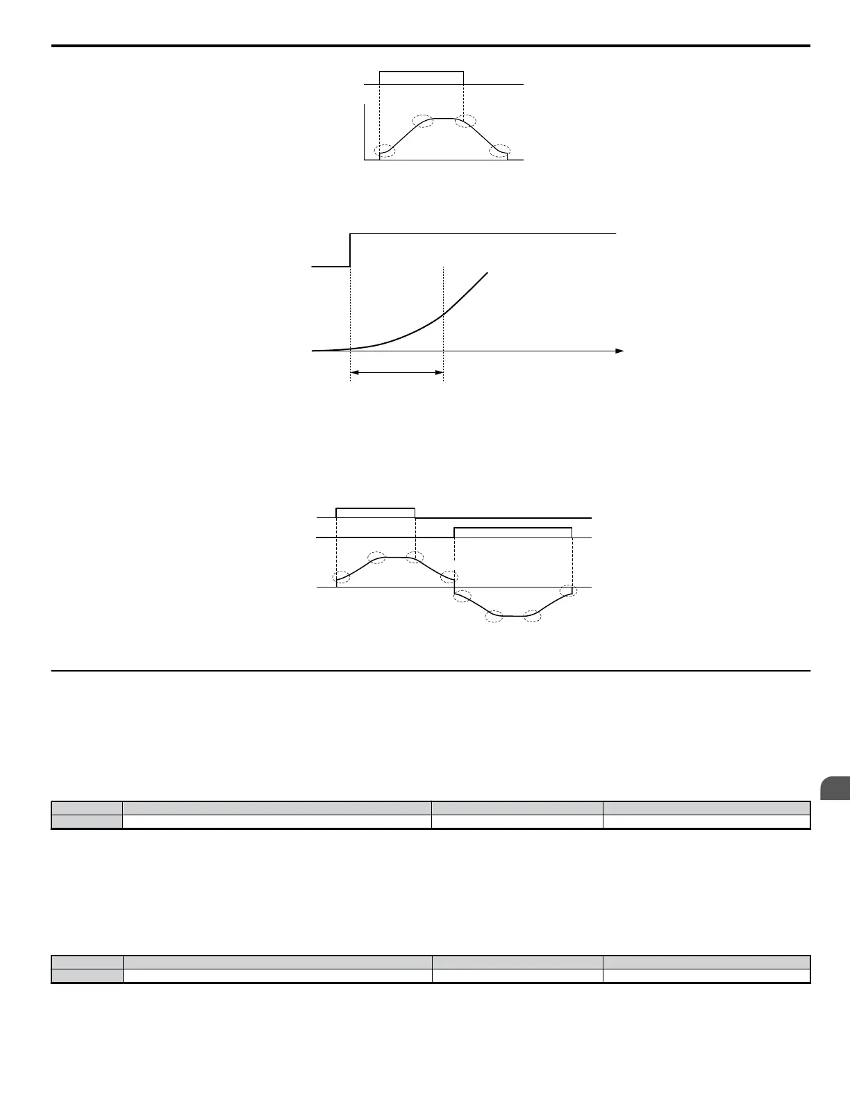
ON
OFF
Time
Run
Command
Output
Frequency
Figure 5.22 S-Curve Characteristics Timing Diagram
Note: Setting the S-curve will increase the acceleration and deceleration times.
Detailed Description
output frequency
output frequency
S-curve characteristic time (Tsc)
TIME
frequency reference
Figure 5.23 S-Curve Characteristic Timing Diagram
Acceleration and deceleration times increase with S-curve characteristics:
Actual accel = accel time setting + (C2-01 + C2-02)/2
Actual decel = decel time setting + (C2-03 + C2-04)/2
S-curve characteristics when switching between forward and reverse are shown in the illustration below.
C2-02
C2-01
C2-03
C2-04
C2-02
C2-01
C2-03
C2-04
FWD run
REV run
output
frequency
Figure 5.24 S-Curve Timing Diagram - FWD/REV Operation
u
C3: Slip Compensation
n
C3-01: Slip Compensation Gain
This parameter is used to increase motor speed to account for motor slip by boosting the output frequency. If the speed is lower than the frequency
reference, increase C3-01. If the speed is higher than the frequency reference, decrease C3-01. Although this parameter rarely needs to be changed,
adjustments might be needed under the following situations:
• If the speed is lower than the frequency reference, increase C3-01.
• If the speed is higher than the frequency reference, decrease C3-01.
No. Parameter Name Setting Range Default
C3-01 Slip Compensation Gain 0.0 to 2.5 Determined by A1-02
Note: Default setting is 0.0 in V/f Control (A1-02 = 0). Default setting is 1.0 in Open Loop Vector Control (A1-02 = 2). This parameter is disabled when using Simple PG in V/f
(H6-01 = 3).
n
C3-02: Slip Compensation Primary Delay Time
Adjusts the filter on the output of the slip compensation function. Increase to add stability, decrease to improve response. This parameter rarely needs to
be changed from its default setting.
• Decrease the setting when the slip compensation response is too slow.
• Increase this setting when the speed is not stable.
No. Parameter Name Setting Range Default
C3-02 Slip Compensation Primary Delay Time 0 to 10000 Determined by A1-02
Note: When using V/f Control (A1-02 = 0), the default setting becomes 2000 ms. When using Open Loop Vector Control (A1-02 = 2), the default setting becomes 200 ms. This
function is not available when using Simple PG in V/f.
5.3 C: Tuning
YASKAWA ELECTRIC SIEP C710606 18A YASKAWA AC Drive – V1000 Technical Manual (Preliminary)
133
5
Parameter Details

 Loading...


