4.6 Basic Drive Setup Adjustments
This section explains the basic settings required for initial drive operation. Checking these basic parameter settings during start-up will help to ensure a
successful drive start-up.
If more information is required for parameters not listed in this section,
Refer to Parameter List on page 293 as required for a complete listing of drive
parameters.
u
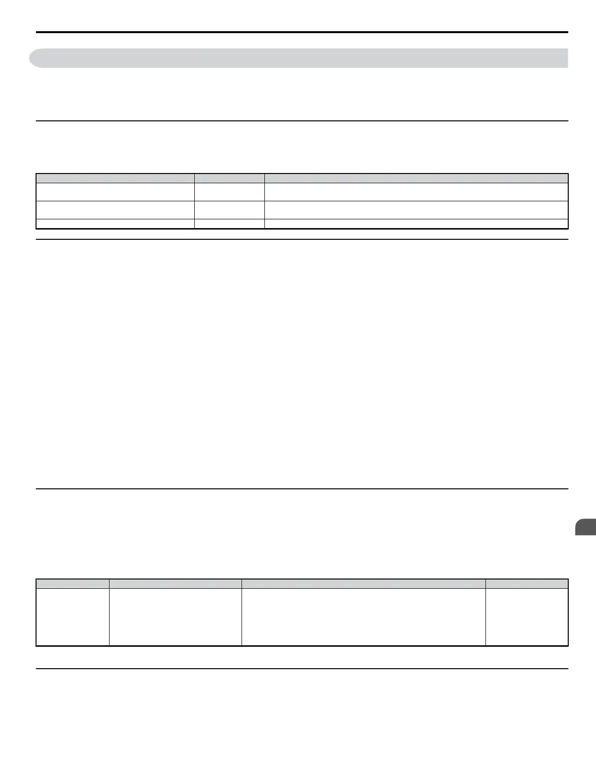
Control Mode Selection: A1-02
n
Available Control Modes
Three motor control modes are available. Select the control mode that best suits the application in which the drive will be used.
Control Mode Parameter Main Applications
V/f Control A1-02 = 0 (default)
• General variable speed applications, particularly useful for running multiple motors from a single drive
• When replacing a drive in which parameter settings are unknown.
Open Loop Vector Control A1-02 = 2
• General variable speed applications
• Applications requiring high precision, high speed control.
PM Open Loop Vector Control A1-02 = 5 Variable torque applications employing permanent magnet motors and energy savings.
u
Initialize Parameter Values: A1-03
Parameter A1-03 (Initialize Parameters) resets all parameters to the original default values.
Note: Save all changed parameter settings by setting o2-03=”1” before initializing the drive. Your settings will be lost if a 2-wire or 3-wire initialization using 2220, or 3330 if
performed without first saving user parameters.
Refer to Backing Up Parameter Values: o2-03 on page 96
n
Different Methods of Drive initialization
1110: Resets all parameters to user-defined default values
A user-initialization resets all parameters to a user-defined set of default values previously saved to the drive. Set parameter o2-03 to “2” to clear those
values.
Note: Set o2-03 to “1” to save the current parameter settings and changes for a “user-initialization.” After saving all parameter setting changes, parameter o2-03 automatically returns
to 0.
Refer to Verifying Parameter Settings and Backing Up Changes on page 96.
2220: 2-Wire Initialization
Returns all parameters to factory default values for 2-wire control.
3330: 3-Wire Initialization
Returns all parameters to factory default values for 3-wire control.
5550: Uploads Parameter Data from the Removable Control Circuit Terminal Board
Replacing either the removable control circuit terminal board or the drive and applying main power may result in an oPE04 fault. If parameter setting
data in the removable control circuit terminal board is correct, set A1-03 to “5550” to upload the data to the drive.
Note: Refer to Run Command Input Selection: b1-02 on page 77 for more information on a 2-wire and 3-wire sequence.
Note: Initializing the drive for 2-wire sequence (A1-03 = 2220) returns all drive parameters to factory settings. Back up all parameters in the event of accidental initialization. the
data with 2-wire sequence returns all the set parameters to the factory settings. Refer to Backing Up Parameter Values: o2-03 on page 96
u
Application Presets: A1-06
The drive features application presets to facilitate the set up of commonly used applications such as a water supply pump, conveyor, exhaust fan, HVAC
fan, compressor, hoist, and crane. Selecting one of these presets automatically sets the required parameters to the optimum values and changes the
appropriate I/O terminal settings for that specific application. Refer to Application Presets on page 70
Verify all I/O signals and external sequences before operating the motor. Refer to Hoist Application Preset Specifics on page 73 when selecting a hoist
application.
Users are able to make further adjustments to these settings using the Setup Mode.
No. Parameter Name Setting Range Default
A1-06 Application Presets
0: General-purpose (A2 parameters are not affected)
1: Water supply pump
2: Conveyor
3: Exhaust fan
4: HVAC fan
5: Air compressor
6: Hoist
7: Crane (hoist, traverse)
0 <1>
<1> All general-purpose parameters are accessible when A1-06 = 0.
u
DWEZ Function Selection: A1-07
DriveWorksEZ is an independent software package that can be used to operate and monitor the drive with a 2 ms scan. It is fully compatible with all types
of serial communication software available on the market.
4.6 Basic Drive Setup Adjustments
YASKAWA ELECTRIC SIEP C710606 18A YASKAWA AC Drive – V1000 Technical Manual (Preliminary)
75
4
Start-Up Programming
& Operation

 Loading...


