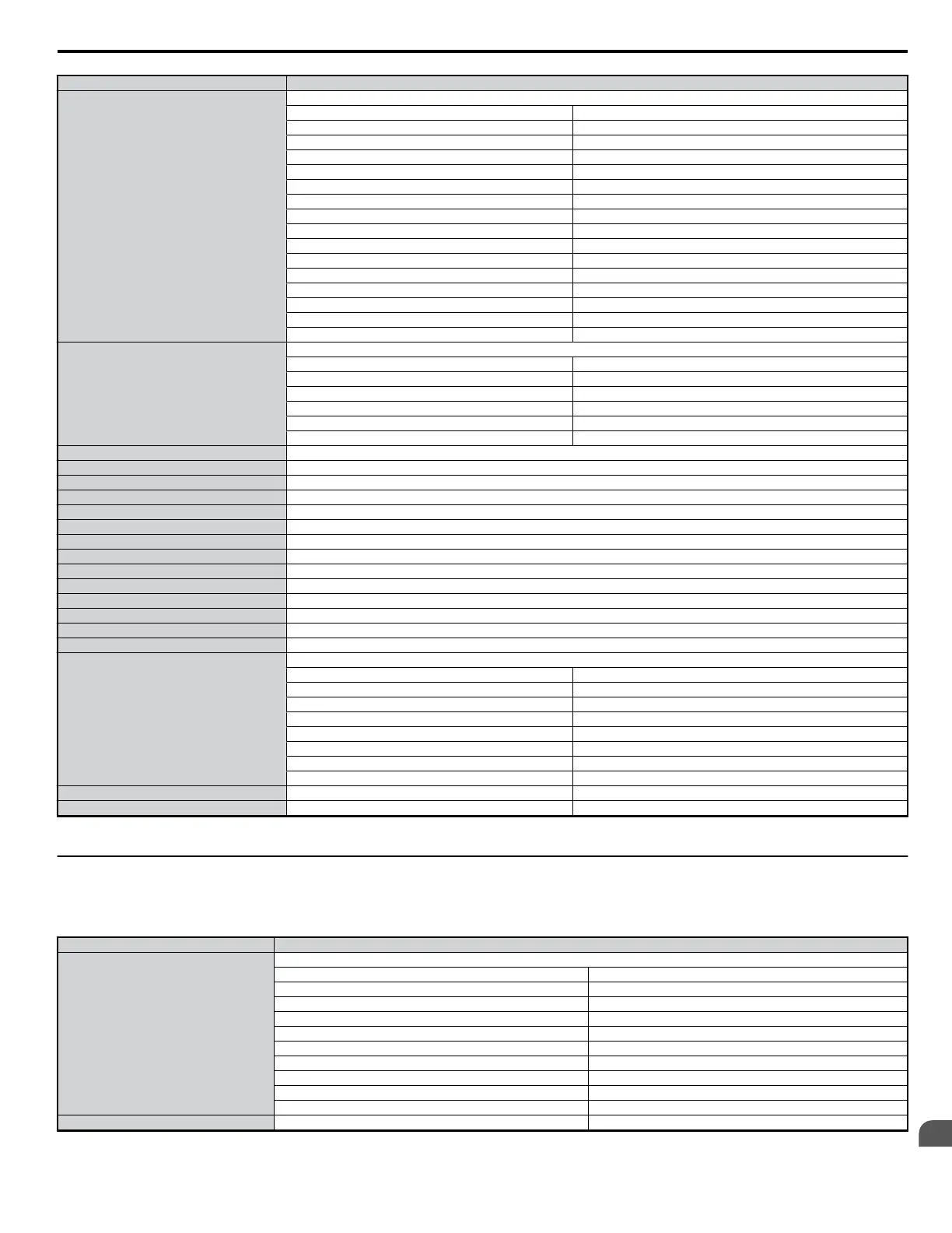
Register No. Contents
002CH
Drive Status 2
bit 0 During Run
bit 1 Zero Speed
bit 2 Speed Agree
bit 3 User Speed Agree
bit 4 Frequency Detection 1
bit 5 Frequency Detection 2
bit 6 Drive Ready
bit 7 During Undervoltage
bit 8 During Baseblock
bit 9 Frequency Reference from Operator Keypad
bit A Run Command from Operator Keypad
bit B Over/Undertorque 1, 2
bit C Frequency Reference Loss
bit D During Fault Restart
bit E Fault
bit F Communication Timeout
002DH
Output Terminal Status (U1-11)
bit 0 Multi-Function Contact Output (terminal MA/MB-MC)
bit 1 Multi-Function Photocoupler Output 1 (terminal P1 - PC)
bit 2 Multi-Function Photocoupler Output 2 (terminal P2 - PC)
bit 3 - 6 Reserved
bit 7 Fault Contact (terminal MA/MB-MC)
bit 8 to bit F Reserved
002EH Reserved
002FH Frequency Reference Bias (UP2, DOWN2) 1000/100%
0030H Reserved
0031H DC Bus Voltage (U1-07)
0032H Torque Monitor (units: 1/1%)
0033H Reserved
0034H Product Code 1 [ASCII] V O
0035H Product Code 2 [ASCII] A O
0036H Reserved
0037H Reserved
0038H PID Feedback (100% / max. output frequency; 1/0.1% resolution; not signed)
0039H PID Input (100% / max. output frequency; 1/0.1% resolution; signed)
003AH PID Output (100% / max. output frequency; 1/0.1% resolution; signed)
003B to 003CH Reserved
003DH
Communications Error Contents*
bit 0 CRC Error
bit 1 Data Length Error
bit 2 Reserved
bit 3 Parity Error
bit 4 Overrun Error
bit 5 Framing Error
bit 6 Timeout
bit 7 to bit F Reserved
003EH Output Frequency Revolutions per Minute
003FH Output Frequency 0.01% Units
*The contents of a communication error are saved until fault is reset.
u
Broadcast Messages
Data can be written from the controller to all slave devices at the same time.
The slave address in a broadcast command message must be set to 00H. All slaves will receive the message, but will not respond.
Register No. Contents
0001H
Digital Input Command
bit 0 Forward Run (0: Stop 1: Run)
bit 1 Direction Command (0: Forward, 1: Reverse)
bit 2, 3 Reserved
bit 4 External Fault (set by H1-01)
bit 5 Fault Reset (set by H1-02)
bit 6 to bit B Reserved
bit C Multi-Function Contact Input S5
bit D Multi-Function Contact Input S6
bit E Multi-Function Contact Input S7
bit F Reserved
0002H Frequency Reference 30000/100%
Note: See the following page for information on Enter Command Data (0900H, 0910H).
C.6 MEMOBUS/Modbus Data Table
YASKAWA ELECTRIC SIEP C710606 18A YASKAWA AC Drive – V1000 Technical Manual (Preliminary)
339
C
MEMOBUS/Modbus
Communications

 Loading...


