V/f Pattern 2
E4-07 Motor 2 Motor Iron-Core Saturation Coefficient 1 E4-15 Torque Compensation Gain - Motor 2
n
E3-01: Motor 2 Control Method Selection
Selects the control method for motor 2.
No. Parameter Name Setting Range Default
E3-01 Motor 2 Control Method Selection
0: V/f Control
2: Open Loop Vector Control
0
Note: Motor 2 cannot be a permanent magnet motor. The OL1 operation selection set to L1-01 applies to both motor 1 and motor 2.
n
E3-04 to E3-10
The default settings for parameters E3-04 through E3-10 change according to the control method used. The values shown in the table below are the defaults
when operating in V/f Control.
No. Parameter Name Setting Range Default
E3-04 Motor 2 Max Output Frequency 40.0 to 400.0
60.0 Hz
*2
E3-05 Motor 2 Max Voltage (VMAX)
0.0 to 255.0
*1
200.0 V
*2
E3-06 Motor 2 Base Frequency (FA) 0.0 to 400.0
60.0 Hz
*2
E3-07 Motor 2 Mid Output Frequency (FB) 0.0 to 400.0
3.0 Hz
*2
E3-08 Motor 2 Mid Output Frequency Voltage (VC)
0.0 to 255.0
*1
16.0 V
*2
E3-09 Motor 2 Minimum Output Frequency (FMIN) 0.0 to 400.0
1.5 Hz
*2
E3-10 Motor 2 Minimum Output Frequency Voltage (VMIN)
0.0 to 255.0
*1
9.0 V
*2
*1. These values are for 200 V class drives. Double these values when using a 400 V class unit.
*2. The default value is determined by the control method (A1-02). Values listed here are for V/f Control.
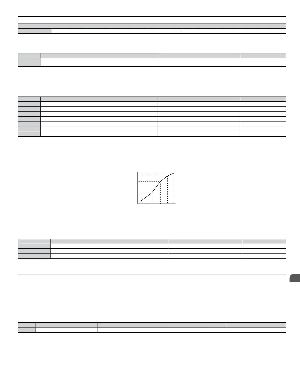
To set V/f characteristics in a straight line, set the same values for E3-07 and E3-09. In this case, the setting for E3-08 will be disregarded. Be sure that
the four frequencies are set in the following manner or else a fault will occur:
E3-04 (FMAX) greater than or equal to E3-06 (FA) > E3-07 (FB) > E3-09 (FMIN)
Output (V)
Frequency (Hz)
E3-05
E3-12
E3-13
E3-08
E3-10
E3-09
E3-07
E3-06
E3-11
E3-04
Figure 5.37 V/f Pattern for Motor 2
n
E3-11 to E3-13
These parameters rarely need to be changed. Adjust only when fine-tuning the V/f pattern to maintain constant output.
No. Parameter Name Setting Range Default
E3-11 Motor 2 Mid Output Frequency 2 0.0 to 400.0 0.0 Hz
E3-12 Motor 2 Mid Output Frequency Voltage 2
0.0 to 255.0
*1
0.0 Vac
E3-13 Motor 2 Base Voltage (VBASE)
0.0 to 255.0
*1
0.0 Vac
*2
*1. These values are for 200 V class drives. Double these values when using a 400 V class unit.
*2. This value will be the same as the motor rated voltage set to T1-03 after Auto-Tuning is performed.
u
E4: Motor 2 Parameters
A single drive is capable of operating two separate motors with different capacities and different V/f characteristics. E4 parameters are for setting up
motor 2. In Open Loop Vector Control, E4 parameters are set automatically during the Auto-Tuning process. These parameters may need to be set manually
if there is a problem performing Auto-Tuning.
n
E4-01: Motor 2 Rated Current
The motor rated current is used by the drive to protect the motor and for proper control when using Open Loop Vector. The drive calculates this value
automatically during the Auto-Tuning process.
No. Parameter Name Setting Range Default
E4-01 Motor 2 Rated Current Between 10 and 200% of the drive rated current. Determined by o2-04
Note: Set the lower and higher digits to the value corresponds to the capacity of the drive: 11 kW or less: Sets the lower 2 digits, 11 kW or higher: Set to the lowest digit
n
E4-02: Motor 2 Rated Slip
This parameter sets the motor rated slip frequency in units of 0.01 Hz. The drive calculates this value is automatically during Rotational Auto-Tuning.
For information on calculating the motor rated slip, see the description on E2-02.
5.5 E: Motor Parameters
YASKAWA ELECTRIC SIEP C710606 18A YASKAWA AC Drive – V1000 Technical Manual (Preliminary)
151
5
Parameter Details

 Loading...


