6.9 Troubleshooting Without Fault Display
This section is for troubleshooting problems that do not trip an alarm or fault.
u
Cannot Change Parameter Settings
Cause Possible Solutions
The drive is running the motor (i.e., the Run command is present).
• Stop the drive and switch over to the Programming Mode.
• Most parameters cannot be edited during run.
The Access Level is set to restrict access to parameter settings. • Set the Access Level to allow parameters to be edited (A1-02 = 2).
The operator is not in the Parameter Setup Mode (the LED screen will
display “PAr”).
• See what mode the LED parameter is current set for.
• Parameters cannot be edited when in the Setup Mode (“STUP”). Switch modes so that “PAr” appears on the screen.
A multi-function contact input terminal is set to allow or restrict
parameter editing (H1-01 through H1-10 = 1B).
• When the terminal is open, parameters cannot be edited.
• Turn on the multi-function contact input set to 1B.
The wrong password was entered.
• If the password entered to A1-04 does not match the password saved to A1-05, then drive settings cannot be changed.
• Reset the password.
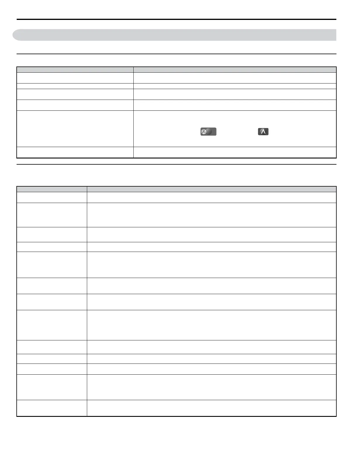
If you cannot remember the password:
•
Display parameter A1-04. Press the
STOP
button while pressing at the same time. Parameter A1-05 will
appear.
• Set a new password to parameter A1-05.
Undervoltage was detected.
• Check the drive input power voltage by looking at the DC bus voltage (U1-07).
• Check all main circuit wiring.
u
Motor Does Not Rotate Properly after Pressing RUN Button or After Entering External Run Command
n
Motor Does Not Rotate
Cause Possible Solutions
The drive is not in the Drive Mode.
• Check if the DRV light on the LED operator is lit.
• Enter the Drive Mode to begin operating the motor. Refer to The Drive and Programming Modes on page 61.
The LO/RE button was pushed.
Stop the drive and check if the correct frequency reference source is selected. If the operator keypad shall be the source, the LO/RE button LED must be
on, if the source is REMOTE, it must be off.
Take the following steps to solve the problem:
• Push the LO/RE button.
• If o2-01 is set to 0, then the LO/RE button will be disabled.
Auto-Tuning has just completed.
• When Auto-Tuning has completed, the drive is switched back to the Programming Mode. The Run command will not be accepted unless the drive is
in the Drive Mode.
• Use the LED operator to enter the Drive Mode. Refer to The Drive and Programming Modes on page 61.
A Fast-Stop was executed and has not yet
been reset.
Reset the Fast-Stop command.
Settings are incorrect for the source that
provides the run command.
Check parameter b1-02 (Run Command Selection).
Set b1-02 so that it corresponds with the correct run command source.
0: LED/LCD operator
1: Control circuit terminal (default setting)
2: MEMOBUS/Modbus communications
3: Option card
One of the Safety Inputs is open.
• Check for a short-circuit between terminals H1 and HC.
• See if one of the Safety Inputs is open.
• Correct any faulty wiring.
There is faulty wiring in the control circuit
terminals.
• Check the wiring for the control terminal.
• Correct wiring mistakes.
• Check the input terminal status monitor (U1-10).
The drive has been set to accept the
frequency reference from the incorrect
source.
Check parameter b1-01 (Frequency Reference Selection 1).
Set b1-01 to the correct source of the frequency reference.
0: LED operator
1: Control circuit terminal (default setting)
2: MEMOBUS/Modbus communications
3: Option card
4: Pulse train input (RP)
The terminal set to accept the main speed
reference is set to the incorrect voltage and/
or current.
Check DIP switch S1. Next assign the correct input level to terminal A2 (H3-09). Refer to Terminal A2 Switch on page 50.
Selection for the sink/source mode is
incorrect.
Check DIP switch S3. Refer to Sinking/Sourcing Mode Switch on page 48.
Frequency reference is too low.
• Check the frequency reference monitor (U1-01).
• Increase the frequency by changing the maximum output frequency (E1-09).
Multi-function analog input is set up to
accept gain for the frequency reference,
but no voltage (current) has been provided.
• Check the multi-function analog input settings.
• Check if analog input A1 or A2 is set for frequency reference gain (H3-02/10 = 1). If so, check if the correct signal is applied to the terminal. The gain
and the frequency reference will be 0 if no signal is applied to the gain input.
• Check if H3-02 and H3-10 have been set to the proper values.
• Check if the analog input value has been set properly.
The STOP button was pressed when the
drive was started from a REMOTE source.
• When the STOP button is pressed, the drive will decelerate to stop.
• Switch off the run command and then re-enter a run command.
• The STOP button is disabled when o2-02 is set to 0.
6.9 Troubleshooting Without Fault Display
248
YASKAWA ELECTRIC SIEP C710606 18A YASKAWA AC Drive – V1000 Technical Manual (Preliminary)

 Loading...


