3.11 Braking Resistor
Dynamic braking (DB) helps bring the motor to a smooth and rapid stop when working with high inertia loads. As the drive lowers the frequency of a
motor with high inertia connected, regeneration occurs. This can cause an overvoltage situation when the regenerative energy flows back into the DC bus
capacitors. A braking resistor prevents these overvoltage faults.
NOTICE: Do not allow unqualified personnel to use the product. Failure to comply could result in damage to the drive or braking circuit. Carefully review the braking resistor
instruction manual when connecting a braking option to the drive.
Note: The braking circuit must be sized properly in order to dissipate the power required to decelerate the load in the desired time. Ensure that the braking circuit can dissipate the
energy for the set deceleration time prior to running the drive.
Use a thermal overload relay or an over-temperature contact to interrupt input power to the drive in the event the braking resistor overheats.
In the event of a possible thermal overload, the relay will trigger the input contactor and prevent the braking resistor from burning up.
u
Installation
WARNING! Fire Hazard. The braking resistor connection terminals are B1 and B2. Do not connect a braking resistor directly to any other terminals. Improper wiring connections
could result in death or serious injury by fire. Failure to comply may result in damage to the braking circuit or drive.
NOTICE: Connect braking resistors to the drive as shown in the I/O wiring examples. Improperly wiring braking circuits could result in damage to the drive or equipment.
n
Installation Procedure
1.
Disconnect all electrical power to the drive and wait at least five minutes before servicing the drive and any connected components.
2.
Remove drive front cover.
3.
Use a voltmeter to verify that voltage is disconnected from incoming power terminals and that the DC bus no longer holds a charge.
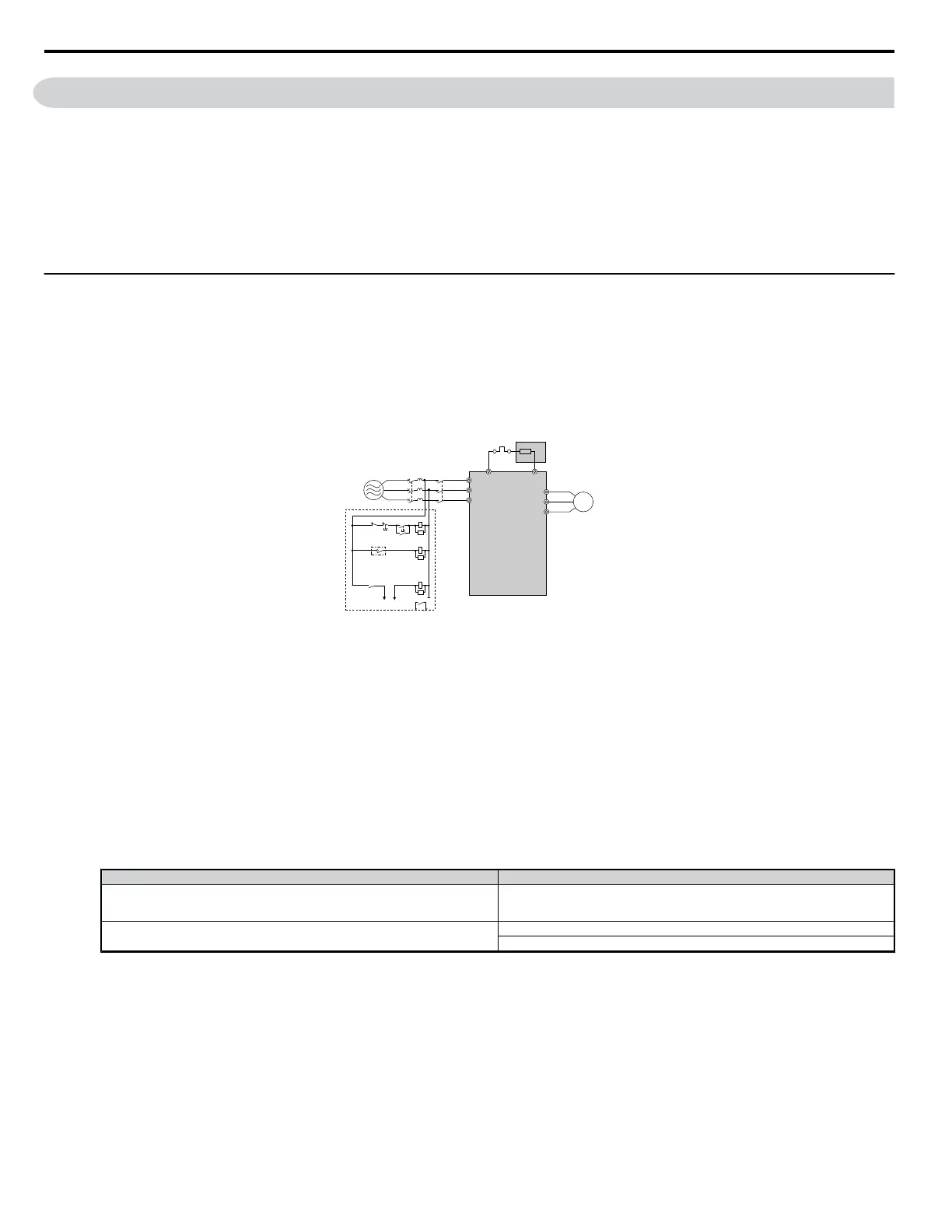
Power
supply
Thermal
relay
Motor
Drive
Braking resistor
Thermal relay switch for
external braking resistor
Fault contact
MC
SA
SA
SA
MCON
MC
OFFTHRX
THRX
TRX
MC
TRX
MA MC
R/L1
B1 B2
S/L2
T/L3
U/T1
V/T2
W/T3
MCCB
Figure 3.30 Connecting a Braking Resistor
4.
Follow manufacturer instructions to connect the resistor unit to the drive using proper wire gauge according to local electrical codes.
Power leads for the remote mount resistors generate high levels of electrical noise; group these signal leads separately.
5.
Mount the resistor unit on a noncombustible surface. Maintain minimum side and top clearances according to resistor manufacturer instructions.
WARNING! Fire Hazard. Do not use improper combustible materials. Failure to comply could result in death or serious injury by fire. Attach the drive or braking resistors
to metal or other noncombustible material.
6.
Reinstall drive covers and resistor covers, if provided.
7.
Set parameter L3-04 = “0” or “3” to disable stall prevention during deceleration.
Set parameter L8-01= “1” to enable overheat protection when using Yaskawa heatsink mounted braking resistor. Set L8-01 = “0” for other braking
resistor types.
Set parameter L3-04 = “3” to generate the shortest possible deceleration time.
Table 3.16 Braking Resistor Settings
Parameter Settings
L8-01: Internal Dynamic Braking Resistor Protection selection
0: Disabled. The drive will not provide overheat protection.
Supply separate means of overheat protection.
1: Enabled. Braking Resistor is protected from overheat.
L3-04: Stall Prevention During Deceleration <1>
0: Stall prevention disabled.
3: Stall prevention enabled with a braking resistor. <2>
<1> Select either 0 or 3.
<2> This setting cannot be used in OLV control for PM motor.
8.
Operate the system and verify the required deceleration rate is obtained during dynamic braking or stopping.
3.11 Braking Resistor
52
YASKAWA ELECTRIC SIEP C710606 18A YASKAWA AC Drive – V1000 Technical Manual (Preliminary)

 Loading...


