n
Input Voltage Setting Value: E1-01
The input voltage level determines the overvoltage detection level and the operation level of the braking transistor as shown in the table below.
Voltage Setting Value of E1-01
(Approximate Values)
OV Detection
Level
Braking Transistor
Operation Level
UV Detection Level
Desired AC Voltage
during KEB
Voltage Level for OV
Suppression, Stall
Prevention
200 V Class all settings 410 V 394 V
190 V
(single-phase=160 V)
240 V 370 V
400 V Class
setting ≥ 400V 820 V 788 V 380 V 480 V 740 V
setting < 400V 740 V 708 V 350 V 440 V 660 V
Note: This data is for an internal dynamic braking resistor of 0.1 to 18.5 kW. For larger units, see “Dynamic Braking Resistor Unit for VARISPEED-600 Series, TOBPC72060000.”
u
V/f Pattern Selection: E1-03
Parameter E1-03 is only available when using V/f Control. It allows the user to set the required V/f pattern and drive output voltage. When running a
high-speed or special-purpose motor, this function fine tunes the amount of torque required for the load. Select the V/f pattern from 15 fixed V/f patterns
or 1 user-programmable V/f pattern.
No. Parameter Name Description Setting Range Default
E1-03 V/f Pattern Selection
0 to E: Select from 15 preset V/f patterns.
F: Custom V/f pattern (allows use of E1-04 through E1-10).
0 to F F
n
Setting Instructions for Setting a V/f Pattern
1.
Set the input voltage for the drive.
Refer to Drive Input Voltage Setting: E1-01 on page 83.
2.
Select one of the two following V/f patterns:
• *Select one of the 15 preset V/f patterns (setting = 0 through E)
• **Select the Custom V/f pattern (setting = F)
3.
In case of *, the following parameters are automatically set.
In case of **, the following parameters are adjustable.
E1-04 (Max Output Frequency), E1-05 (Max Voltage), E1-06 (Base Frequency), E1-07 (Mid Output Frequency), E1-08 (Mid Output Frequency
Voltage), E1-09 (Min Output Frequency), E1-10 (Min Output Frequency Voltage)
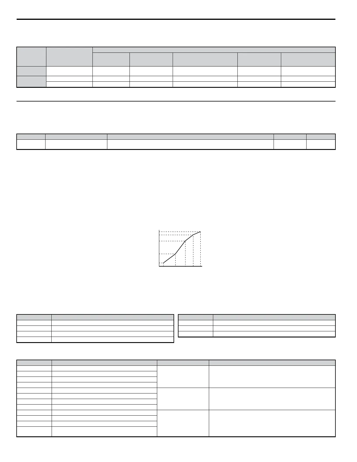
Output Voltage (V)
Frequency (Hz)
E1-05
E1-12
E1-13
E1-08
E1-10
E1-09 E1-07 E1-06 E1-11 E1-04
Figure 4.24 V/f Pattern
n
Selecting a Preset V/f Pattern
There are two types of V/f patterns: a method to select one of the 15 presets (set value: 0 to E) and a method to select arbitrary V/f pattern (set value: F).
Refer to
Table 4.20 .
No. Parameter Name
E1-04 Maximum Output Frequency (FMAX)
E1-05 Maximum Voltage (VMAX)
E1-06 Base Frequency (FA)
E1-07 Mid Output Frequency (FB)
No. Parameter Name
E1-08 Mid Output Frequency Voltage (VC)
E1-09 Minimum Output Frequency (FMIN)
E1-10 Minimum Output Frequency Voltage (VMIN)
Note: The default setting for the V/f pattern is for a custom V/f pattern (E1-03 = F).
Table 4.20 V/f Patterns
Setting Specification Characteristic Application
0 50 Hz
Constant torque
For general purpose applications, torque remains constant regardless of speed
changes.
1 (F) 60 Hz
2 60 Hz (with 50 Hz base)
3 72 Hz (with 60 Hz base)
4 50 Hz, Heavy Duty 3
Reduced or variable torque
For applications where torque changes with the speed like fans, pumps, and
others that require reduced torque relative to the load.
5 50 Hz, Heavy Duty 2
6 60 Hz, Heavy Duty 3
7 60 Hz, Heavy Duty 2
8 50 Hz, mid starting torque
High starting torque
High starting should be selected only when:
• Wiring between the drive and motor exceeds 150 m
• Large amount of starting torque is required
• AC reactor is installed
• motor exceeds the largest motor recommended for that drive used
9 50 Hz, high starting torque
A 60 Hz, mid starting torque
B 60 Hz, high starting torque
4.6 Basic Drive Setup Adjustments
84
YASKAWA ELECTRIC SIEP C710606 18A YASKAWA AC Drive – V1000 Technical Manual (Preliminary)

 Loading...


