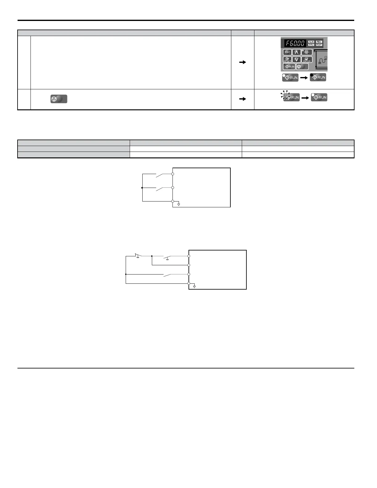
Step Display/Result
4. The motor should accelerate up to 6 Hz while the RUN light is on.
off on
5.
Press the
STOP
key to stop the motor. The RUN light will flash until the motor comes to a complete stop.
flashing
off
n
Run the Drive using Digital Input Terminals: b1-02 = 1
This setting uses the digital input terminals to enter the run command. The factory setting is a 2-wire sequence.
Using a 2-Wire Sequence
Digital Input Terminals ON OFF
S1 Forward Run Stop
S2 Reverse Run Stop
Drive
Forward Run
S1
S2
SC
Reverse Run
Digital Input Common
Figure 4.15 Example Wiring Diagram for 2-Wire Sequence
Using a 3-Wire Sequence
When H1-05 (Multi-Function Digital Input Terminal S5 Function Selection) = 0, the functions of terminals S1 and S2 are set to 3-wire sequence, and the
multi-function input terminal becomes forward/reverse run command terminal.
S1
S2
S5
SC
Run Command
(runs when open)
Drive
Stop Switch
(N.C.)
Run Switch
(N.O.)
Stop Command
(stops when closed)
FWD/REV Command
(multi-function input)*
Digital Input Common
Figure 4.16 Example Wiring Diagram for 3-Wire Sequence Using Terminal S5
*When terminal S5 is open, the motor rotates forward. When closed, the motor rotates in reverse.
WARNING! When 3-Wire sequence is used, set the drive to 3-Wire sequence before wiring the control terminals and ensure parameter b1-17 is set to 0 (drive does not accept a
run command at power up (default)). If the drive is wired for 3-Wire sequence but set up for 2-Wire sequence (default) and if parameter b1-17 is set to 1 (drive accepts a Run
command at power up), the motor will rotate in reverse direction at power up of the drive and may cause injury.
Note:
Refer to Parameter List on page 293 for a list of digital input functions. After performing a 3-wire initialization (A1-03 = “3”), the drive will automatically assign the forward/
reverse command to terminal S5.
CAUTION! The motor will begin rotating as soon as the power is switched on. Proper precautions must be taken to ensure that the area around the motor is safe prior to powering
up the drive. Failure to do so may result in minor or moderate injury.
Note: Run by Turning on/off the Power Supply. For safety reasons, the drive is initially set up not to accept a run command at power up (b1-17 = "0"). If a run command is issued
at power up, the RUN indicator LED will flash quickly. To change this and have the run command issued by the drive, change parameter b1-17 to 1.
u
Stopping Method Selection: b1-03
When a Stop command is issued, the drive stops the motor using one of four possible methods.
n
Ramp to Stop: b1-03 = 0
When b1-03 = 0, the motor will decelerate to a stop when a stop command is entered. The deceleration time is set by C1-02 (Deceleration Time 1).
Refer
to Acceleration/Deceleration: C1-01 to C1-11 on page 80.
When the output frequency falls below the DC Injection braking start frequency (b2-01) during deceleration, the DC Injection braking current (b2-02)
will be activated for the specified DC Injection time at stop (b2-04).
4.6 Basic Drive Setup Adjustments
78
YASKAWA ELECTRIC SIEP C710606 18A YASKAWA AC Drive – V1000 Technical Manual (Preliminary)

 Loading...


