n
d2-03: Master Speed Reference Lower Limit
Unlike frequency reference lower limit (d2-02) which will affect the frequency reference no matter where it is sourced from (i.e., analog input, preset
speed, Jog speed, etc.), the frequency reference lower limit (d2-03) sets a low speed threshold that will only affect the analog input (terminals A1 and A2)
that is the active master speed frequency.
Set as a percentage of the maximum output frequency.
Note: The lower limits for the Jog frequency, multi-step speed settings, and 2-step speed settings do not change. When lower limits are set to both the frequency reference (d2-02)
and the main frequency reference (d2-03), the drive uses the greater of those two values as the lower limit.
No. Parameter Name Setting Range Default
d2-03 Master Speed Reference Lower Limit 0.0 to 110.0 0.0%
u
d3: Jump Frequency
n
d3-01 to d3-04: Jump Frequencies 1, 2, 3
n
d3-04: Jump Frequency Width
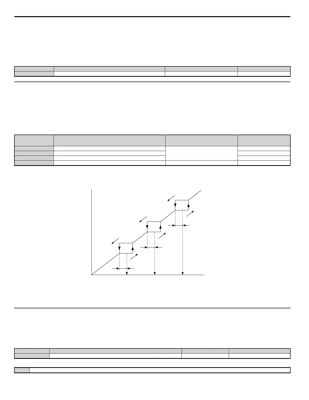
In order to avoid continuous operation at a speed that causes resonance in driven machinery, the drive can be programmed with Jump Frequencies that
will not allow continued operation within specific frequency ranges. If a speed is commanded that falls within a dead band, or Jump Frequency, the drive
will clamp the frequency reference just below the dead band and only accelerate past it when the commanded speed rises above the upper end of the dead
band, for increasing references.
No. Parameter Name Setting Range Default
d3-01 Jump Frequency 1
0.0 to 400.0
0.0 Hz
d3-02 Jump Frequency 2 0.0 Hz
d3-03 Jump Frequency 3 0.0 Hz
d3-04 Jump Frequency Width 0.0 to 20.0 1.0 Hz
Detailed Description
The figure below shows the relationship between the Jump Frequency and the output frequency.
Output
Frequency
Frequency
Reference
Jump
Frequency
Width (d3-04)
Jump
Frequency 3
d3-03
Jump
Frequency 2
d3-02
Jump
Frequency 1
d3-01
frequency
reference
decreases
frequency
reference
increases
Jump
Frequency
Width (d3-04)
Jump
Frequency
Width (d3-04)
Note: The drive will not operate within the specified deadband range for the Jump Frequency. Although the drive quickly accelerates (or decelerates) the motor through the Jump
Frequency frequency range, it still maintains the accel/decel times sets to C1-01 and C1-02. When using more than one Jump Frequency, make sure that d3-01 is greater than
or equal to d3-02 is greater than or equal to d3-03. Setting parameters d3-01 to d3-03 to 0 essentially disables the Jump Frequency.
u
d4: Frequency Reference Hold
Determines how bias values affect the frequency reference, and also whether or not the frequency reference is saved when the power is shut off.
n
d4-01: Frequency Reference Hold Function Selection
This function is available when the multi-function inputs “accel/decel ramp hold” or “Up/Down” commands are selected (H1-oo = A or 10 and 11).
Determines whether or not the frequency reference is saved when the power supply is shut off.
No. Parameter Name Setting Range Default
d4-01 Frequency Reference Hold Function Selection 0, 1 0
Detailed Description
0 Disabled: Starts the motor from 0.
5.4 d: Reference Settings
142
YASKAWA ELECTRIC SIEP C710606 18A YASKAWA AC Drive – V1000 Technical Manual (Preliminary)

 Loading...


