No. Parameter Name Setting Range Default
E2-07 Motor Iron-Core Saturation Coefficient 1 0.00 to 0.50 0.50
n
E2-08: Motor Iron-Core Saturation Coefficient 2
This parameter sets the motor iron saturation coefficient at 75% of the magnetic flux. If Rotational Auto-Tuning completes successfully, then this value
is automatically calculated.
No. Parameter Name Setting Range Default
E2-08 Motor Iron-Core Saturation Coefficient 2 E2-07 to 0.75 0.75
n
E2-09: Motor Mechanical Loss
This parameter sets to the motor mechanical loss as a percentage of motor rated power (kW) capacity.
No. Parameter Name Setting Range Default
E2-09 Motor Mechanical Loss 0.0 to 10.0 0.0%
Adjust this setting in the following circumstances:
• When torque loss is large due to motor bearing friction.
• When the torque loss in the load is large.
The setting for the mechanical loss is added to the torque.
n
E2-10: Motor Iron Loss for Torque Compensation
This parameter sets the motor iron loss in watts.
No. Parameter Name Setting Range Default
E2-10 Motor Iron Loss for Torque Compensation 0 to 65535 Determined by o2-04
n
E2-11: Motor Rated Output
This parameter sets the motor rated power in kW. If rotational Auto-Tuning completes successfully, this value is automatically calculated. Remember
that 1 hp = 0.746 kilowatts.
No. Parameter Name Setting Range Default
E2-11 Motor Rated Output 0.00 to 650.00 Determined by o2-04
n
E2-12: Motor Iron-Core Saturation Coefficient 3
This parameter sets the motor rated power in kW. If rotational Auto-Tuning completes successfully, this value is automatically calculated. Remember
that 1 hp = 0.746 kilowatts.
No. Parameter Name Setting Range Default
E2-12 Motor Iron-Core Saturation Coefficient 3 1.30 to 5.00 1.30
u
E3: V/f Characteristics for Motor 2
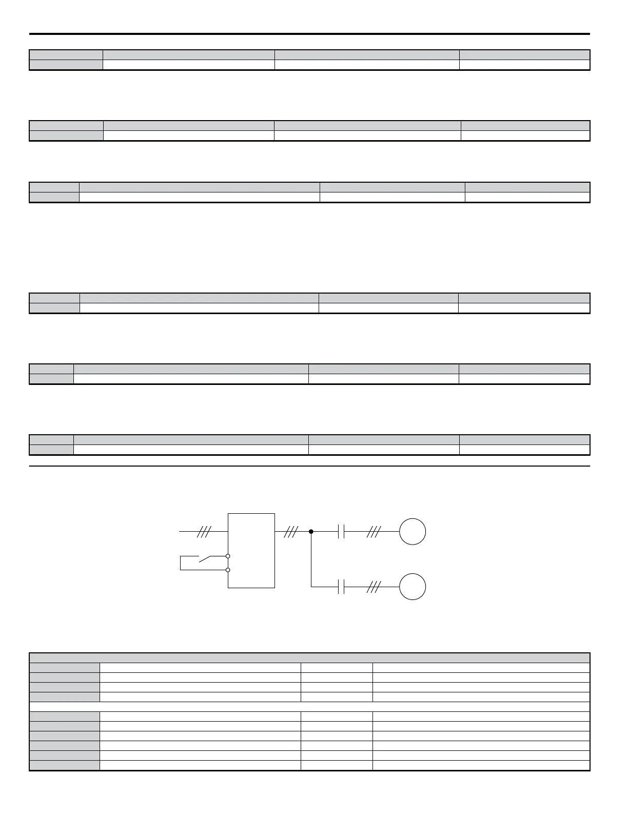
The drive has the capability to control two motors independently. A second motor may be selected using a multi-function contact input (H1-oo = 16).
This parameter select the control method for motor 2. The control method for motor 1 is selected via parameter A1-02.
M
M
DRIVE
motor 1
motor 2
motor switch signal
Figure 5.36 Motor Selection
When motor 2 is selected, the following parameters become available:
Table 5.13 Parameters for Motor 2
V/f Pattern 2
E3-01 Motor 2 Control Method Selection E3-07 Motor 2 Minimum Output Frequency (FB)
E3-04 Motor 2 Max Voltage (VMAX) E3-08 Motor 2 Mid Output Frequency Voltage (VC)
E3-05 Motor 2 Max Frequency (FMAX) E3-09 Motor 2 Minimum Output Frequency (FMIN)
E3-06 Motor 2 Base Frequency (FA) E3-10 Motor 2 Mid Output Frequency Voltage 2
Motor 2 Settings
E4-01 Motor 2 Rated Current E4-08 Motor 2 Motor Iron-Core Saturation Coefficient 2
E4-02 Motor 2 Rated Slip E4-09 Motor 2 Mechanical Loss
E4-03 Motor 2 Rated No-Load Current E4-10 Motor 2 Iron Loss
E4-04 Motor 2 Motor Poles E4-11 Motor 2 Rated Capacity
E4-05 Motor 2 Line-to-Line Resistance E4-12 Motor 2 Iron-Core Saturation Coefficient 3
E4-06 Motor 2 Leakage Inductance E4-14 Motor 2 Slip Compensation Gain
5.5 E: Motor Parameters
150
YASKAWA ELECTRIC SIEP C710606 18A YASKAWA AC Drive – V1000 Technical Manual (Preliminary)

 Loading...


