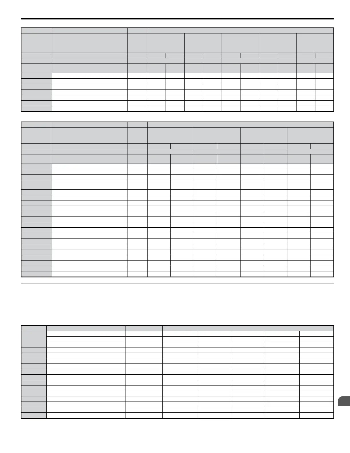
No. Description Unit Default Settings
−
Model CIMR-Vo
− 2A0001 2A0002 2A0004 2A0006 2A0010
C6-01 Normal/Heavy Duty Sel. − HD ND HD ND HD ND HD ND HD ND
o2-04 kVA Selection Hex. 60 61 62 63 65
E2-11 (E4-11,
T1-02)
Motor rated power kW 0.1 0.2 0.2 0.4 0.4 0.75 0.75 1.1 1.5 2.2
L2-04 Momentary power loss voltage recovery time s 0.3 0.3 0.3 0.3 0.3 0.3 0.3 0.3 0.3 0.3
L2-05 UV detection voltage V dc 190 190 190 190 190 190 190 190 190 190
L3-24 Motor acceleration time s 0.178 0.178 0.178 0.178 0.178 0.142 0.142 0.142 0.166 0.145
L8-02 Overheat alarm level
°C
110 110 110 110 115 115 100 100 100 100
L8-09 Ground fault selection − 0 0 0 0 0 0 0 0 0 0
L8-38 Carrier frequency reduction selection − 1 1 1 1 1 1 1 1 1 1
n1-03 Hunting Prevention Time Constant ms 10 10 10 10 10 10 10 10 10 10
Table B.7 Three-Phase 400V Class Drives - Default Settings by Drive Capacity and Normal/Heavy Duty Selection
No. Description Unit Default Settings
−
Model CIMR-Vo
− 4A0001 4A0002 4A0004 4A0005
C6-01 Normal/Heavy Duty − HD ND HD ND HD ND HD ND
o2-04 kVA Selection Hex. 91 92 93 94
E2-11 (E4-11,
T1-02)
Motor rated power kW 0.2 0.4 0.4 0.75 0.75 1.5 1.5 2.2
b3-06 Speed Search current 1 − 1.0 1.0 0.5 0.5 0.5 0.5 0.5 0.5
b8-04 Energy saving coefficient − 713.8 576.4 576.4 447.4 447.4 338.8 338.8 313.6
C6-02 Carrier frequency − 3 7 3 7 3 7 3 7
E2-01 (E4-01,
T1-04)
Motor rated current A 0.6 1 1 1.6 1.6 3.1 3.1 4.2
E2-02 (E4-02) Motor rated slip Hz 2.5 2.9 2.9 2.6 2.6 2.5 2.5 3
E2-03 (E4-03) Motor no load current A 0.4 0.6 0.6 0.8 0.8 1.4 1.4 1.5
E2-05 (E4-05) Motor line-to-line resistance Ω 83.94 38.198 38.198 22.459 22.459 10.1 10.1 6.495
E2-06 (E4-06) Motor leakage inductance % 21.9 18.2 18.2 14.3 14.3 18.3 18.3 18.7
E2-10 (E4-10) Motor Iron Loss W 12 14 14 26 26 53 53 77
E5-01 Motor Code hex FFFF FFFF FFFF FFFF FFFF FFFF FFFF FFFF
L2-02 Momentary power loss ride-through time s 0.1 0.1 0.1 0.1 0.2 0.2 0.3 0.3
L2-03 Momentary power loss base block time s 0.2 0.2 0.2 0.3 0.3 0.4 0.4 0.5
L2-04 Momentary power loss voltage recovery time s 0.3 0.3 0.3 0.3 0.3 0.3 0.3 0.3
L2-05 UV detection voltage V dc 380 380 380 380 380 380 380 380
L3-24 Motor acceleration time s 0.178 0.178 0.178 0.142 0.142 0.166 0.166 0.145
L8-02 Overheat alarm level
°C
110 110 110 110 110 110 90 90
L8-09 Ground fault selection − 0 0 0 0 0 0 0 0
L8-35 Enclosure/Mounting selection − 0 0 0 0 0 0 0 0
L8-38 Carrier frequency reduction selection − 1 1 1 1 1 1 1 1
n1-03 Hunting Prevention Time Constant ms 10 10 10 10 10 10 10 10
u
Parameters that Change with the Motor Code Selection
The following tables show parameters and default settings that change with the motor code selection E5-01 when Open Loop Vector for PM motors is
used.
n
Yaskawa Pico Motor (SPM motor)
Table B.8 1800 rpm Yaskawa Pico Motor Settings
Par. Description Unit Default Settings
E5-01
Motor Code − 0002 0003 0005 0006 0008
Voltage class Rated power − 200 Vac 0.4 kW 200 Vac 0.75 kW 200 Vac 1.5 kW 200 Vac 2.2 kW 200 Vac 3.7 kW
Rated speed min-1 1800 1800 1800 1800 1800
E5-02 Motor rated power kW 0.4 0.75 1.5 2.2 3.7
E5-03 Motor rated current A 2.1 4.0 6.9 10.8 17.4
E5-04 Motor pole number – 8 8 8 8 8
E5-05 Motor winding resistance
Ω
2.47 1.02 0.679 0.291 0.169
E5-06 d-axis inductance mH 12.7 4.8 3.9 3.6 2.5
E5-07 q-axis inductance mH 12.7 4.8 3.9 3.6 2.5
E5-09 Induction voltage constant 1 mVsec/rad 0 0 0 0 0
E5-24 Induction voltage constant 2 mV/min-1 62.0 64.1 73.4 69.6 72.2
E1-04 Maximum output frequency Hz 120 120 120 120 120
E1-05 Maximum output voltage V 200.0 200.0 200.0 200.0 200.0
E1-06 Base voltage Hz 120 120 120 120 120
E1-09 Minimum output voltage Hz 6 6 6 6 6
L3-24 Motor acceleration time s 0.064 0.066 0.049 0.051 0.044
B.2 Parameter Table
YASKAWA ELECTRIC SIEP C710606 18A YASKAWA AC Drive – V1000 Technical Manual (Preliminary)
325
B
Parameter List

 Loading...


