No. Description Unit Default Settings
− Model CIMR-Vo − BA0001 BA0002 BA0003
C6-01 Normal/Heavy Duty Sel. Hex. HD ND HD ND HD ND
o2-04 kVA Selection − 30 31 32
E2-11 (E4-11,
T1-02)
Motor rated power kW 0.1 0.2 0.2 0.4 0.4 0.75
E2-01 (E4-01,
T1-04)
Motor rated current A 0.6 1.1 1.1 1.9 1.9 3.3
E2-02 (E4-02) Motor rated slip Hz 2.5 2.6 2.6 2.9 2.9 2.5
E2-03 (E4-03,
T1-09)
Motor no load current A 0.4 0.8 0.8 1.2 1.2 1.8
E2-05 (E4-05) Motor line-to-line resistance Ω 35.98 20.56 20.56 9.842 9.842 5.156
E2-06 (E4-06) Motor leakage inductance % 21.6 20.1 20.1 18.2 18.2 13.8
E2-10 (E4-10) Motor Iron Loss W 6 11 11 14 14 26
E5-01 Motor code hex FFFF FFFF FFFF FFFF 0002 0002
L2-02 Momentary power loss ride-through time s 0.1 0.1 0.1 0.1 0.1 0.1
L2-03 Momentary power loss base block time s 0.2 0.2 0.2 0.2 0.2 0.3
L2-04 Momentary power loss voltage recovery time s 0.3 0.3 0.3 0.3 0.3 0.3
L2-05 UV detection voltage V dc 160 160 160 160 160 160
L3-24 Motor acceleration time s 0.178 0.178 0.178 0.178 0.178 0.142
L8-02 Overheat alarm level
°C
115 115 115 115 110 110
L8-09 Ground fault selection − 0 0 0 0 0 0
L8-38 Carrier freq. reduction sel. − 1 1 1 1 1 1
n1-03 Hunting Prev. Time Const. ms 10 10 10 10 10 10
No. Description Unit Default Settings
− Model CIMR-Vo − BA0006 BA0010 BA0012 BA0018
C6-01 Normal/Heavy Duty − HD HD ND HD ND HD
o2-04 kVA Selection Hex. 33 34 35 37
E2-11 (E4-11,
T1-02)
Motor rated power kW 0.75 1.1 1.5 2.2 2.2 3.0 3.7
b3-06 Speed Search current 1 − 0.5 0.5 0.5 0.5 0.5 0.5 0.5
b8-04 Energy saving coefficient − 223.7 169.4 169.4 156.8 156.8 136.4 122.9
C6-02 Carrier frequency − 4 7 3 7 3 7 3
E2-01 (E4-01,
T1-04)
Motor rated current A 3.3 6.2 6.2 8.5 8.5 11.4 14.0
E2-02 (E4-02) Motor rated slip Hz 2.5 2.6 2.6 2.9 2.9 2.7 2.73
E2-03 (E4-03) Motor no load current A 1.8 2.8 2.8 3 3 3.7 4.5
E2-05 (E4-05) Motor line-to-line resistance Ω 5.156 1.997 1.997 1.601 1.601 1.034 0.771
E2-06 (E4-06) Motor leakage inductance % 13.8 18.5 18.5 18.4 18.4 19 19.6
E2-10 (E4-10) Motor Iron Loss W 26 53 53 77 77 91 112
E5-01 Motor Code hex 0003 0003 0005 0005 0006 0006 0008
L2-02 Momentary power loss ride-through time s 0.2 0.2 0.3 0.3 0.5 0.5 1.0
L2-03 Momentary power loss base block time s 0.3 0.4 0.4 0.5 0.5 0.5 0.6
L2-04 Momentary power loss voltage recovery time s 0.3 0.3 0.3 0.3 0.3 0.3 0.3
L2-05 UV detection voltage V dc 160 160 160 160 160 160 160
L3-24 Motor acceleration time s 0.142 0.142 0.166 0.145 0.145 0.145 0.154
L8-02 Overheat alarm level
°C
105 105 100 100 95 95 100
L8-09 Ground fault selection − 0 0 0 0 0 0 0
L8-38 Carrier frequency reduction selection − 1 1 1 1 1 1 1
n1-03 Hunting Prevention Time Constant ms 10 10 10 10 10 10 10
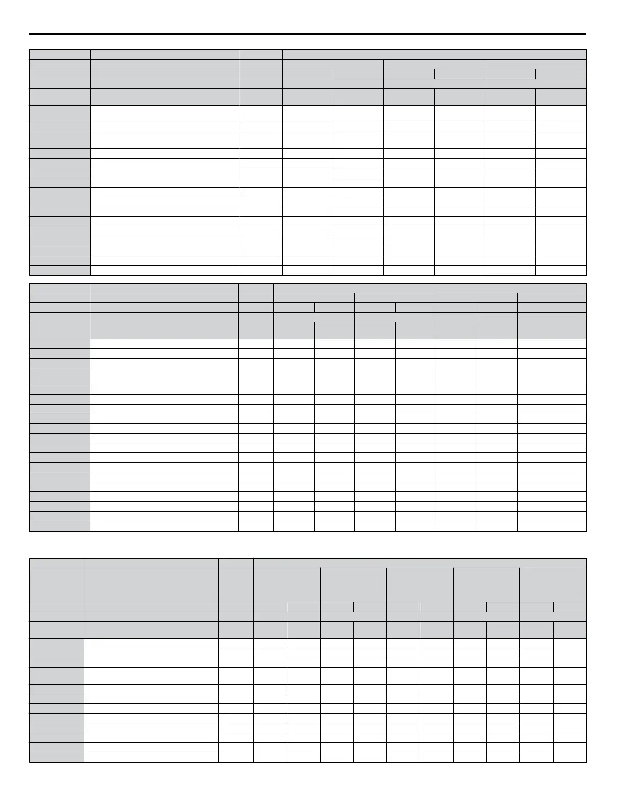
Table B.6 Three-Phase, 200 V Class Drives
Default Settings by Drive Capacity and Normal/Heavy Duty Selection
No. Description Unit Default Settings
−
Model CIMR-Vo
− 2A0001 2A0002 2A0004 2A0006 2A0010
C6-01 Normal/Heavy Duty Sel. − HD ND HD ND HD ND HD ND HD ND
o2-04 kVA Selection Hex. 60 61 62 63 65
E2-11 (E4-11,
T1-02)
Motor rated power kW 0.1 0.2 0.2 0.4 0.4 0.75 0.75 1.1 1.5 2.2
b3-06 Speed Search current 1 − 1.0 1.0 1.0 1.0 1.0 1.0 0.5 0.5 0.5 0.5
b8-04 Energy saving coefficient − 481.7 356.9 356.9 288.2 288.2 223.7 223.7 196.6 169.4 156.8
C6-02 Carrier frequency − 4 7 4 7 4 7 4 7 3 7
E2-01 (E4-01,
T1-04)
Motor rated current A 0.6 1.1 1.1 1.9 1.9 3.3 3.3 4.9 6.2 8.5
E2-02 (E4-02) Motor rated slip Hz 2.5 2.6 2.6 2.9 2.9 2.5 2.5 2.6 2.6 2.9
E2-03 (E4-03) Motor no load current A 0.4 0.8 0.8 1.2 1.2 1.8 1.8 2.3 2.8 3.0
E2-05 (E4-05) Motor line-to-line resistance Ω 35.98 20.56 20.56 9.842 9.842 5.156 5.156 3.577 1.997 1.601
E2-06 (E4-06) Motor leakage inductance % 21.6 20.1 20.1 18.2 18.2 13.8 13.8 18.5 18.5 18.4
E2-10 ( E4-10) Motor Iron Loss W 6 11 11 14 14 26 26 38 53 77
E5-01 Motor Code hex FFFF FFFF FFFF FFFF 0002 0002 0003 0003 0005 0005
L2-02 Momentary power loss ride-through time s 0.1 0.1 0.1 0.1 0.1 0.1 0.2 0.2 0.3 0.3
L2-03 Momentary power loss base block time s 0.2 0.2 0.2 0.2 0.2 0.3 0.3 0.4 0.4 0.5
B.2 Parameter Table
324
YASKAWA ELECTRIC SIEP C710606 18A YASKAWA AC Drive – V1000 Technical Manual (Preliminary)

 Loading...


