Problem Parameter No. Countermeasure Default Value Suggested Setting
• Poor motor torque at low speeds
• Poor speed response
• Motor instability at motor start.
Mid Output Voltage A (E1-08)
Minimum Output Voltage
(E1-10)
• If motor torque and speed response are too slow, increase the
setting.
• If the motor exhibits excessive instability at start-up, reduce the
setting.
Note: The default value is for 200 V class units. Double this value
when using a 400 V class drive. When working with a relatively light
load, increasing this value too much can create an excessively high
of a torque reference.
E1-08: 12.0 V
<1>
E1-10: 2.5 V
<1>
Initial ±2 V
<1> Default settings change when the Control Method is changed (A1-02) or a different V/f pattern is selected using parameter E1-03. The default setting shown is for V/f Control.
When using OLV Motor Control, leave the torque compensation gain (C4-01) at its default setting of 1.00. To increase speed precision during regeneration
in OLV Motor Control, enable slip compensation during regeneration (C3-04 = “1”).
u
Motor Hunting and Oscillation Control Parameters
In addition to the parameters discussed in
V/f Pattern Selection: E1-03, the following parameters indirectly affect motor hunting and oscillation.
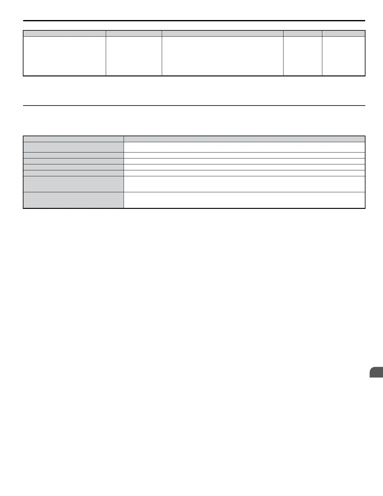
Table 6.3 Parameters that Affect Control Performance in Applications
Name (Parameter No.) Application
Dwell Function (b6-01 through b6-04)
Prevents motor speed loss by maintaining the output frequency when working with heavy loads or when there is powerful backlash on the
machine side.
Accel/Decel Time (C1-01 through C1-11) Adjusting accel and decel times will affect the torque presented to the motor during acceleration or deceleration.
S-Curve Characteristics (C2-01 through C2-04) Prevents shock at the beginning and end of acceleration and deceleration.
Jump Frequency (d3-01 through d3-04) Skips over the resonant frequencies of connected machinery.
Analog Filter Time Constant (H3-13) Prevents fluctuation in the analog input signal due to noise.
Stall Prevention (L3-01 through L3-06, L3-11)
• Prevents motor speed loss and overvoltage. Used when the load is too heavy and also during sudden acceleration/deceleration.
• Adjustment is not normally required because Stall Prevention is enabled as a default. Disable Stall Prevention during deceleration
(L3-04 = “0”) when using a braking resistor.
Torque Limits (L7-01 through L7-04, L7-06, L7-07)
• Sets the maximum torque for Open Loop Vector Control.
• Ensure that the drive capacity is greater than the motor capacity when increasing this setting. Be careful when reducing this value
because motor speed loss may occur with heavy loads.
6.2 Motor Performance Fine Tuning
YASKAWA ELECTRIC SIEP C710606 18A YASKAWA AC Drive – V1000 Technical Manual (Preliminary)
225
6
Troubleshooting

 Loading...


