u
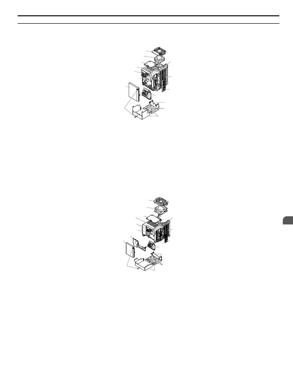
IP20/NEMA Type 1 Enclosure
n
Single-phase AC200 V CIMR-V
oBA0001F ~ 0003F
Three-phase AC200 V CIMR-Vo2A0001F ~ 0006F
A
B
C
D
E
F
G
H
I
J
K
L
N
O
M
A – Fan cover
B – Mounting hole
C – Heatsink
D – Optional 24 V DC power supply
connector cover
E – Terminal board Refer to Control
Circuit Terminal Block Functions on
page 44
F – Bottom cover screws
G – Rubber bushing
H – Bottom front cover
I – Front cover screws
J – Front cover
K – Comm port
L – LED operator Refer to Using the
Digital LED Operator on page 58
M – Case
N – Top cover
O – Cooling fan Refer to Drive Cooling
Fans on page 261
Figure 1.4 Exploded View of IP20/NEMA Type 1 Components
Three-phase AC200 V CIMR-Vo2A00062F
n
Single-phase AC200 V CIMR-V
oBA0006F ~ 0018F
Three-phase AC200 V CIMR-Vo2A0010F ~ 0020F
Three-phase AC400 V CIMR-Vo4A0001F ~ 0011F
A
B
C
D
E
F
H
G
I
J
K
L
M
O
P
N
A – Fan cover
B – Mounting hole
C – Heatsink
D – Optional 24 V DC power supply
connector cover
E – Terminal board Refer to Control
Circuit Terminal Block Functions on
page 44
F – Cover screws
G – Rubber bushing
H – Bottom cover
I – Front cover screws
J – Front cover
K – Terminal cover
L – Comm port
M – LED operator Refer to Using the
Digital LED Operator on page 58
N – Case
O – Top cover
P – Cooling fan Refer to Drive Cooling
Fans on page 261
Figure 1.5 Exploded view of IP20/NEMA Type 1 Components
Three-phase AC200 V CIMR-Vo2A0012F
Note:
CIMR-VoBA0018F is supplied with two built-in cooling fans.
1.4 Component Names
YASKAWA ELECTRIC SIEP C710606 18A YASKAWA AC Drive – V1000 Technical Manual (Preliminary)
21
1
Receiving

 Loading...


