L1-01 Setting Motor Type Overload Tolerance Cooling Fan Capacity
Electrothermal Protection (100%
motor overload)
A: Typical maximum speed for Yaskawa motor frame number 200LJ and greater
B: Typical maximum speed for Yaskawa motor frame numbers 160MJ – 180LJ
C: Typical maximum speed for Yaskawa motor frame number 132MHJ or less
D: Typical maximum speed for Yaskawa motor frame number 132MJ or less
Notes on Motor Protection
• Motor protection meeting UL and cUL standards is achieved with the motor overload protection time (L1-02) set to factory default setting. Normally,
L1-02 (Motor Overload Protection Time) does not require setting. If the motor overload tolerance is clear, set the overload protection time at hot start
according to the motor. To detect overload earlier, decrease the setting.
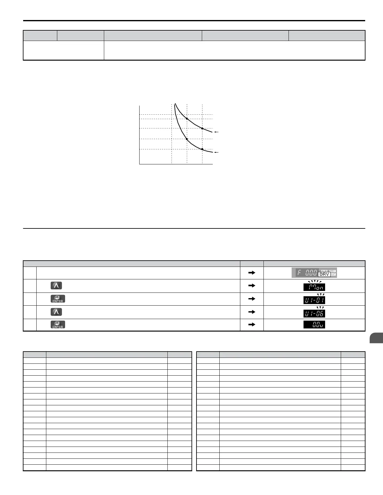
Note:
Figure 4.27 illustrates motor protection operation time characteristics.
Cold Start
Hot Start
Motor Current (%)
E2-01 = 100%
10
7
3
1
0.4
0.1
0 100 200150
Operation Time (minutes)
Figure 4.27 Motor Protection Operation
• Disable motor protection (L1-01 = 1) when running multiple motors from the same drive. Attach a thermal relay for each motor to provide overload
protection.
• Use L1-13 (Continuous Electrothermal Operation Selection) to select whether the electrothermal value is “held” or “not held” when power supply is
turned off. Default setting is 1 (Enabled).
• In the case of a general purpose (standard) motor, the cooling capability is reduced at a low speed. Motor overload protection (OL1) may occur in
frequencies lower than motor rated current. Use an exclusive-use or inverter-duty motor to operate the drive at rated current at low frequency.
u
Drive Status Monitors: U1-01 to U6-19
Parameter group U displays various data regarding the operating status of the drive.
The following example demonstrates viewing output voltage reference (U1-06).
Step Display/Result
1. Turn on the power to the drive. The initial display appears.
2.
Press until “Monitor Display” appears.
3.
Press to enter the Parameter Setting Screen.
4.
Press until U1-06 appears.
5.
Press to display the voltage reference. The Output Voltage Reference appears.
Refer to Parameter List on page 293 for more details about Drive Status Monitors.
Table 4.22 Drive Status Monitors
No. Parameter Name Page
U1-01 Frequency Reference 318
U1-02 Output Frequency 318
U1-03 Output Current 318
U1-04 Control Mode 318
U1-05 Motor Speed 318
U1-06 Output Voltage Reference 318
U1-07 DC Bus Voltage 318
U1-08 Output Power 318
U1-09 Torque Reference 318
U1-10 Input Terminal Status 319
U1-11 Output Terminal Status 319
U1-12 Drive Status 319
U1-13 Terminal A1 Input Voltage 319
U1-14 Terminal A2 Input Voltage 319
U1-16 Output Frequency after SoftStart 319
U1-18 oPE Fault 319
U1-19 MEMOBUS/Modbus Error Code 320
U1-24 Input Pulse Monitor 320
U1-25 Software Number (Flash) 320
No. Parameter Name Page
U1-26 Software Number (ROM) 320
U2-01 Current Fault 320
U2-02 Previous Fault 320
U2-03 Frequency Reference at Previous Fault 320
U2-04 Output Frequency at Previous Fault 320
U2-05 Output Current at Previous Fault 320
U2-06 Motor Speed at Previous Fault 320
U2-07 Output Voltage at Previous Fault 320
U2-08 DC Bus Voltage at Previous Fault 320
U2-09 Output Power at Previous Fault 320
U2-10 Torque Reference at Previous Fault 320
U2-11 Input Terminal Status at Previous Fault 320
U2-12 Output Terminal Status at Prev. Fault 320
U2-13 Drive Operation Status at Pre. Fault 320
U2-14 Cumulative Operation Time at Previous Fault 320
U2-15 Soft Starter Speed Reference at Previous Fault 320
U2-16 Motor q-Axis Current at Previous Fault 320
U2-17 Motor d-Axis Current at Previous Fault 320
U3-01 Most Recent Fault 320
4.6 Basic Drive Setup Adjustments
YASKAWA ELECTRIC SIEP C710606 18A YASKAWA AC Drive – V1000 Technical Manual (Preliminary)
89
4
Start-Up Programming
& Operation

 Loading...


