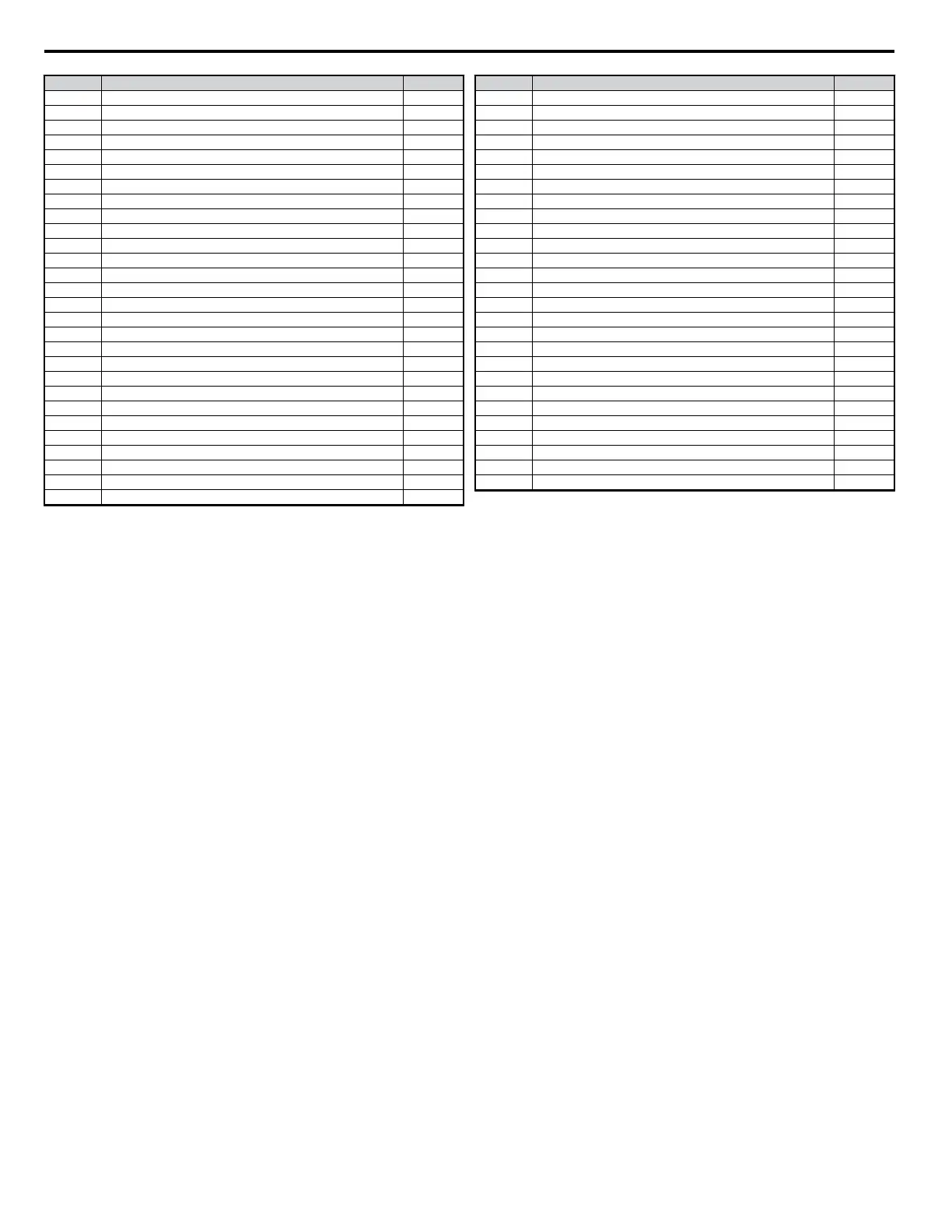
No. Parameter Name Page
U3-02 2nd Most Recent Fault 320
U3-03 3rd Most Recent Fault 320
U3-04 4th Most Recent Fault 320
U3-05 5th Most Recent Fault 320
U3-06 6th Most Recent Fault 320
U3-07 7th Most Recent Fault 320
U3-08 8th Most Recent Fault 320
U3-09 9th Most Recent Fault 320
U3-10 10th Most Recent Fault 320
U3-11 Cumulative Operation Time at Most Recent Fault 320
U3-12 Cumulative Operation Time at 2nd Most Recent Fault 320
U3-13 Cumulative Operation Time at 3rd Most Recent Fault 320
U3-14 Cumulative Operation Time at 4th Most Recent Fault 320
U3-15 Cumulative Operation Time at 5th Most Recent Fault 320
U3-16 Cumulative Operation Time at 6th Most Recent Fault 320
U3-17 Cumulative Operation Time at 7th Most Recent Fault 320
U3-18 Cumulative Operation Time at 8th Most Recent Fault 321
U3-19 Cumulative Operation Time at 9th Most Recent Fault 321
U3-20 Cumulative Operation Time at 10th Most Recent Fault 321
U4-01 Accumulated Operation Time 321
U4-02 Number of Run Commands 321
U4-03 Cooling Fan Operation Time 321
U4-05 Capacitor Maintenance 321
U4-07 IGBT Maintenance 321
U4-08 Heatsink Temperature 321
U4-09 LED Check 321
U4-10 kWH, Lower 4 Digits 321
U4-11 kWH, Upper 5 Digits 321
No. Parameter Name Page
U4-13 Peak Hold Current 321
U4-14 Peak Hold Output Frequency 321
U4-16 Motor Overload Estimate (OL1) 321
U4-18 Frequency Reference Selection Results 321
U4-19 Freq. Ref. from MEMOBUS/Modbus Communications 321
U4-20 Option Frequency Reference 321
U4-21 Run Command Selection Results 321
U4-22 MEMOBUS/Modbus Comm. Ref. 321
U4-23 Option Card Reference 321
U5-01 PID Feedback 322
U5-02 PID Input (feedback) 322
U5-03 PID Output 322
U5-04 PID Setpoint 322
U6-01 Torque Reference (Internal) 322
U6-02 Motor Secondary Current (Iq) 322
U6-03 Motor Excitation Current (ld) 322
U6-04 Output of speed control (ASR) (for Simple V/f PG) 322
U6-05 Output voltage reference (Vq) 322
U6-06 Output Voltage Reference (Vd) 322
U6-07 q-axis ACR Output 322
U6-08 d-Axis ACR Output 322
U6-17 Energy Savings Coefficient Calculation Value 322
U6-18 PID Differential Feedback 322
U6-19 PID Adjusted Feedback 322
U6-20 Frequency Ref. Bias (Up/Down 2) 322
U6-21 Offset Frequency 322
U8-oo
Custom Monitors for DriveWorksEZ 322
4.6 Basic Drive Setup Adjustments
90
YASKAWA ELECTRIC SIEP C710606 18A YASKAWA AC Drive – V1000 Technical Manual (Preliminary)

 Loading...


