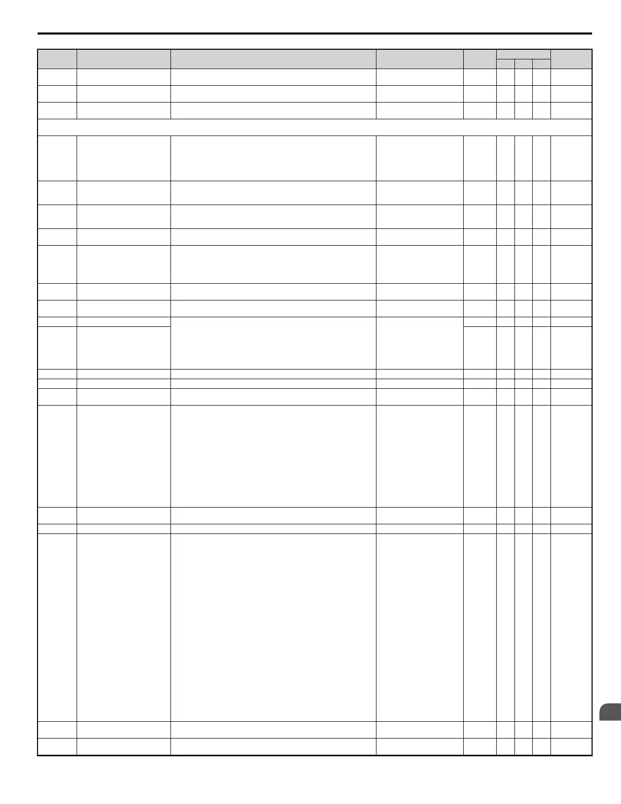
No. Name Description Analog Output Level Unit
Control Mode
Addr. Hex
V/f OLV PM
U3-18
Cumulative Operation Time at
8th Most Recent Fault
Displays the cumulative operation time at the eighth most recent fault. No signal output available 1 h A A A 811E
U3-19
Cumulative Operation Time at
9th Most Recent Fault
Displays the cumulative operation time at the ninth most recent fault. No signal output available 1 h A A A 812
U3-20
Cumulative Operation Time at
10th Most Recent Fault
Displays the cumulative operation time at the tenth most recent fault. No signal output available 1 h A A A 813
U4: Maintenance Monitors
Use U4 parameters to display drive maintenance information.
U4-01 Accumulated Operation Time
Displays the cumulative operation time of the drive. The value for the
cumulative operation time counter can be set in parameter o4-01. Use
parameter o4-02 to determine if the operation time should start as soon
as the power is switched on or only while the run command is present.
The maximum number displayed is 99999, after which the value is reset
to 0.
No signal output avail. 1 h A A A 4C
U4-02 Number of Run Commands
Displays the number of times the run command is entered. Reset the
number of run commands using parameter o4-13. This value will reset
to 0 and start counting again after reaching 65535.
No signal output avail. A A A 76
U4-03 Cooling Fan Operation Time
Displays the cumulative operation time of the cooling fan. The default
value for the fan operation time is set to parameter o4-03. This value will
reset to 0 and start counting again after reaching 65535.
No signal output avail. 1H A A A 67
U4-05 Capacitor Maintenance
Displays main circuit capacitor usage time in in percent of their expected
performance life. Parameter o4-06 resets this monitor.
No signal output avail. 1% A A A 7C
U4-07 IGBT Maintenance
Displays IGBT usage time as a percent of expected performance life.
One of the multi-function contact outputs can be set to close when the
value reaches 50% (H2-oo = 2F), triggering an alarm. One of the multi-
function contact outputs can be set to close when the value reaches 90%
(H2-oo = 10), triggering an alarm. Parameter o4-09 resets this monitor.
No signal output avail. 1% A A A 7D7
U4–08 <60>
Heatsink Temperature Monitors the heatsink for the drive. No signal output avail. 1°C A A A 68
U4-09 LED Check
Lights all segments of the LED to verify that the display is working
properly.
No signal output avail. – A A A 3C
U4-10 kWH, Lower 4 Digits Monitors the drive output power. The value is shown as a 9 digit number
displayed across two monitor parameters, U4-10 and U4-11.
Example:
12345678.9 kWh is displayed as:
U4-10: 678.9 kWh
U4-11: 12345 MWh
Analog monitor: No output signal available.
No signal output avail.
kWh A A A 5C
U4-11 kWH, Upper 5 Digits MWh A A A 5D
U4-13 Peak Hold Current Displays the peak hold current during run. 10 V: Motor rated current 0.01A A A A 7CF
U4-14 Peak Hold Output Frequency Displays the output frequency when operating at the peak hold current. 10 V: Max frequency 0.01Hz A A A 7D0
U4-16
Motor Overload Estimate
(OL1)
100% = OL1 detection level 100% = OL1 detection level 0.1% A A A 7D8
U4-18
Frequency Reference Source
Selection
Displays the source for the frequency reference as XY-nn.
X: indicates which reference is used:
1 = Reference 1 (b1-01)
2 = Reference 2 (b1-15)
Y-nn: indicates the reference source
0-01 = Operator (d1-01)
1-01 = Analog (terminal A1)
1-02 = Analog (terminal A2)
2-02 to 17 = Multi-step speed (d1-02 to 17)
3-01 = MEMOBUS/Modbus comm.
4-01 = Option
5-01 = Pulse Input
6-01 = CASE
7-01 = DWEZ
A A A 7DA
U4-19
Frequency Reference from
MEMOBUS/Modbus Comm.
Displays the frequency reference provided by MEMOBUS/Modbus
(decimal)
A A A 7DB
U4-20 Option Frequency Reference Displays the frequency reference input by an option card (decimal). A A A 7DD
U4-21
Run Command Source
Selection
Displays the source for the Run command as XY-nn.
X: Indicates which Run source is used:
1 = Reference 1 (b1-02)
2 = Reference 2 (b1-16)
Y: Input power supply data
0 = Operator
1 = External terminals
2 = Not used
3 = MEMOBUS/Modbus communications
4 = Option
5 = Not used
6 = CASE
7 = DWEZ
nn: Run command limit status data
00: No limit status.
01: Run command was left on when stopped in the PRG mode.
02: Run command was left on when switching from local to remote
operation.
03: Waiting for the soft charge bypass contactor after the power is
switched on (UV or UV1 flashes after 10 seconds).
04: Waiting for “Run Command Prohibited” time period to end.
05: Fast-stop (digital input (H1-oo = 15), operator)
06: b1-17 (run command given at power-up).
07: During Baseblock while coast to stop with timer
08: Frequency reference is below minimal reference during base block
09: Waiting for Enter command
A A A 7DD
U4-22
MEMOBUS/Modbus
Communications Reference
Displays the drive control data set by MEMOBUS/Modbus
communications register No. 0001H as a 4 digit hexadecimal number.
A A A 7DE
U4-23 Option Card Reference
Displays drive control data set by an option card as a 4 digit hexadecimal
number.
A A A 7DF
B.2 Parameter Table
YASKAWA ELECTRIC SIEP C710606 18A YASKAWA AC Drive – V1000 Technical Manual (Preliminary)
321
B
Parameter List

 Loading...


