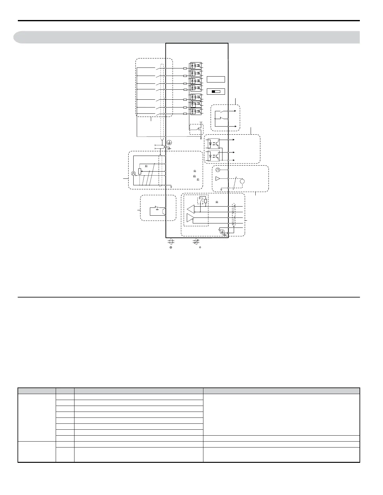
3.7 Control Circuit Wiring
Forward run/stop
Reverse run/stop
External fault
Fault reset
Multi-step
speed 2
Jog reference
0 to +10 Vdc
(2 mA)
DIP
switch S3
Digital inputs
(default setting)
Comm.
connector
Safe Disable
Input
Safety switch
Fault
V1000
Shield ground
terminal
Control circuit
S1
S2
S3
S4
S5
S6
S7
*
1
24 V
0 V
MA
P1
MB
MC
V I
+
24 V 8 mA
*
2
SC
P2
MP
AM
AC
PC
IG
R
+
R
-
S
+
S
-
+
-
AM
HC
H1
RP
+V
A1
A2
AC
Pulse train input
(max. 32 kHz)
0 to +10 V (20 k )
Setting power supply
+10.5 max. 20 mA
0 to +10 V (20 k )
During Run
(photocoupler 1)
Frequency agree
(photocoupler 2)
Photocoupler
output common
Digital output
5 ~ 48 Vdc
2 to 50 mA
(default setting)
Pulse train output
0 to 32 kHz
Analog monitor
output
Digital output
250 Vac, 10 mA to 1 A
30 Vdc, 10 mA to 1 A
(default setting)
MEMOBUS/
Modbus comm.
RS-485/422
Main speed
frequency
reference.
Multi-function
programmable
Multi-step
speed 1
main/aux switch
DIP switch S1
Sink
Source
Termination
resistor
120 , 1/2 W
Monitor
output
Jumper
Option card
connector
DIP
switch
S2
main circuit terminal
shielded line
twisted-pair shielded line
control terminal
Cable shield ground
2 k
(0) 4 to 20 mA (250
)
*
3
Figure 3.18 Control Circuit Connection Diagram
*1. Connected using sequence input signal (S1 to S7) from NPN transistor; Default: sink mode (0 V com)
*2. Use only a +24 V internal power supply in sinking mode; the source mode requires an external power supply.
Refer to I/O Connections on page 48.
*3. Minimum load: 5 Vdc, 10mA (reference value)
NOTICE: Do not solder the ends of wire connections to the drive. Soldered wire connections can loosen over time. Improper wiring practices could result in drive malfunction due
to loose terminal connections.
u
Control Circuit Terminal Block Functions
Drive parameters determine which functions apply to the multi-function digital inputs (S1 to S7), multi-function digital outputs (MA, MB), multi-function
pulse inputs and outputs (RP, MP) and multi-function photocoupler outputs (P1, P2). The default is called out next to each terminal.
Refer to
Figure 3.18 on page 44 .
WARNING! Sudden Movement Hazard. Always check the operation and wiring of control circuits after being wired. Operating a drive with untested control circuits could result in
death or serious injury.
WARNING! Confirm the drive I/O signals and external sequence before starting test run. Setting parameter A1-06 may change the I/O terminal function automatically from the
factory setting.
Refer to Application Presets on page 70. Failure to comply may result in death or serious injury.
NOTICE: Do not switch an input contactor more often than once every 30 minutes. Improper equipment sequencing could shorten useful life of the drive electrolytic capacitors
and circuit relays. Normally the drive I/O should be used to stop and start the motor.
n
Input Terminals
Table 3.6 Control Circuit Input Terminals
Type No. Terminal Name (Function) Function (Signal Level) Default Setting
Multi-Function
Digital Inputs
S1 Multi-function input 1 (Closed: Forward run, Open: Stop)
Photocoupler
24 Vdc, 8 mA
Note: Drive preset to sinking mode. When using source mode, set DIP switch S3 to allow
for a 24 Vdc (±10%) external power supply. Refer to page 48.
S2 Multi-function input 2 (Closed: Reverse run, Open: Stop)
S3 Multi-function input 3 (External fault (N.O.))
S4 Multi-function input 4 (Fault reset)
S5 Multi-function input 5 (Multi-step speed reference 1)
S6 Multi-function input 6 (Multi-step speed reference 2)
S7 Multi-function input 7 (Jog reference)
SC Multi-function input common (Control common) Sequence common
Safety Input
HC Power supply for safety input command +24 Vdc (max 10 mA allowed)
H1 Safety input command
Open: Coast to stop safety input
Closed: Normal operation
Note: Disconnect wire jumper between HC and H1 when using safety input.
3.7 Control Circuit Wiring
44
YASKAWA ELECTRIC SIEP C710606 18A YASKAWA AC Drive – V1000 Technical Manual (Preliminary)

 Loading...


