Setting 7C: Short Circuit Braking, N.O.
Setting 7D: Short Circuit Braking, N.C.
Short Circuit Braking commands (both the N.O. and N.C. terminal settings) are for use with PM Open Loop Vector only.
Status Description
Open Normal operation
Closed Short-Circuit Braking
Setting 7E: Forward Reverse Detection (Simple PG in V/f)
Status Description
Open Forward
Closed Reverse
Assigns the direction of speed feedback to one of the multi-function terminals using the Pulse Train Input.
Setting 90 to 96: DriveWorksEZ Digital Input 1 to 7
Setting 9F: DriveWorksEZ Function Disable (requires A1-07 = 2)
This function is for use with DriveWorksEZ. Contact Yaskawa for more information on DriveWorksEZ.
u
H2: Multi-Function Outputs
n
H2-01: Terminal MA, MB, and MC Function Selection
n
H2-02: Terminal P1 Function Selection
n
H2-03: Terminal P2 Function Selection
The drive has three multi-function output terminals. Set parameters H2-01 to H2-03 between 0 and 192 to assign functions to these terminals. Default
values are listed in the table below.
No. Parameter Name Setting Range Default
H2-01 Terminal MA, MB and MC Function Selection (relay) 0 to 192 E: Fault Closes when a fault occurs (excluding CPF00, CPF01).
H2-02 Terminal P1 Function Selection (open-collector) 0 to 192 0: During RunCloses when the Run command is present or when there is voltage output.
H2-03 Terminal P2 Function Selection (open-collector) 0 to 192 2: Speed Agree 1 (detection width set to L4-02)
Note: If not using an input terminal or if using it in the through-mode, be sure to set that terminal to “F”.
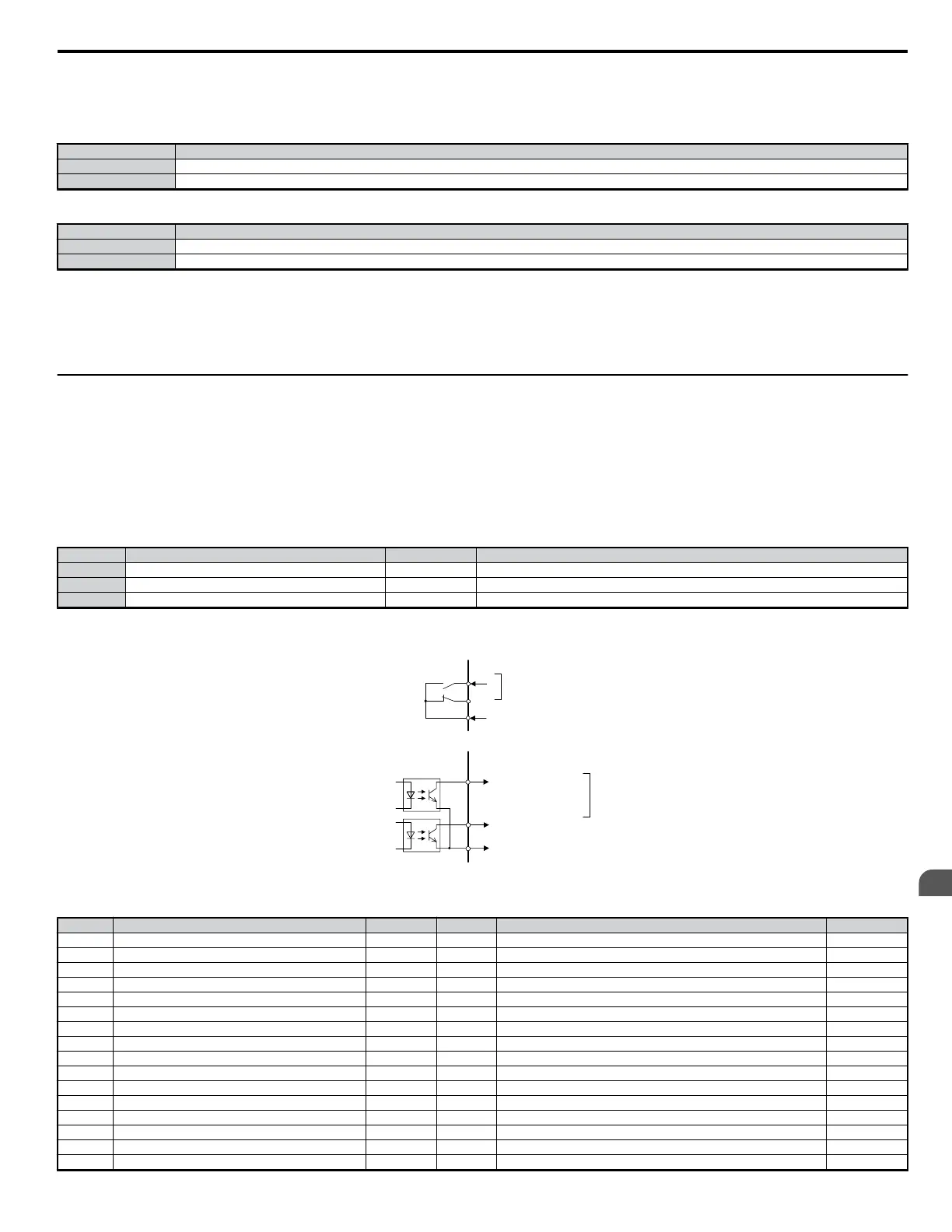
Below is a circuit diagram for the multi-function output terminals.
MA
P1
P2
MB
MC
PC
During Run (photocoupler 1)
Speed Agree (photocoupler 2)
multi-function contact output
250 Vac 10 mA or more: 1 A or less
30 Vdc 10 mA
or more:
1 A or less
standard settings when
shipped from the factory
standard settings when
shipped from the factory
fault
fault
multi-function photocoupler output
5 to 48 Vdc, 50 mA or less
photocoupler output common
Figure 5.49 Multi-Function Output Circuit Diagram
Table 5.18 Multi-Function Output Terminal Settings
Setting Function Page Setting Function Page
0 During Run − 19 Torque Detection 2 (N.C.) −
1 Zero Speed − 1A Reverse Direction −
2 Fref/Fout Agree 1 − 1B Baseblock 2 −
3 Fref/Fset Agree 1 − 1C Motor 2 Selection −
4 Frequency (FOUT) Detection 1 − 1E Restart Enabled −
5 Frequency (FOUT) Detection 2 − 1F Overload OL1 (OL1 Alarm) −
6 Drive Ready − 20 OH Pre alarm −
7 DC Bus Undervoltage − 22 Mechanical Weakening (N.O.) −
8 During Baseblock − 30 During Torque Limit −
9 Option Reference − 37 During Frequency Output −
A Local/Remote − 38 Drive Enable −
B Torque Detection 1 (N.O.) − 39 Watt Hour Pulse Output −
C Loss of Reference − 3C Drive Mode −
D Braking Resistor Fault − 3D Speed Search −
E Fault − 3E PID Feedback Loss −
F Not used − 3F PID Feedback Fault −
5.7 H: Terminal Functions
YASKAWA ELECTRIC SIEP C710606 18A YASKAWA AC Drive – V1000 Technical Manual (Preliminary)
171
5
Parameter Details

 Loading...


