u
E: Motor Parameters
No. Name Description Range Def.
Control Mode
Addr. Hex Pg.
V/f
OL
V
PM
E1: V/f Pattern Characteristics
Use E1 parameters to set V/f characteristics for the motor.
E1-01 <24> Input Voltage Setting
This parameter must be set to the power supply voltage. It sets the maximum
and base voltage used by preset V/f patterns (E1-03 = 0 to E) and adjusts levels
used by certain functions.
WARNING! Drive input voltage (not motor voltage) must be set in E1-01 for
the protective features of the drive to function properly. failure to do so may
result in equipment damage and/or death or personal injury.
155 to 255 230 V S S S 300 83
E1-03 V/f Pattern Selection
Selects a preset V/f pattern.
0: 50 Hz Constant torque 1
1: 60 Hz Constant torque 2
2: 60 Hz Constant torque 3 (50 Hz base)
3: 72 Hz Constant torque 4 (60 Hz base)
4: 50 Hz Variable torque 1
5: 50 Hz Variable torque 2
6: 60 Hz Variable torque 3
7: 60 Hz Variable torque 4
8: 50 Hz High starting torque 1
9: 50 Hz High starting torque 2
A: 60 Hz High starting torque 3
B: 60 Hz High starting torque 4
C: 90 Hz (60 Hz base)
D: 120 Hz (60 Hz base)
E: 180 Hz (60 Hz base)
F: Custom V/f. E1-04 through E1-13 settings define the V/f pattern.
0 to F F A A − 302 —
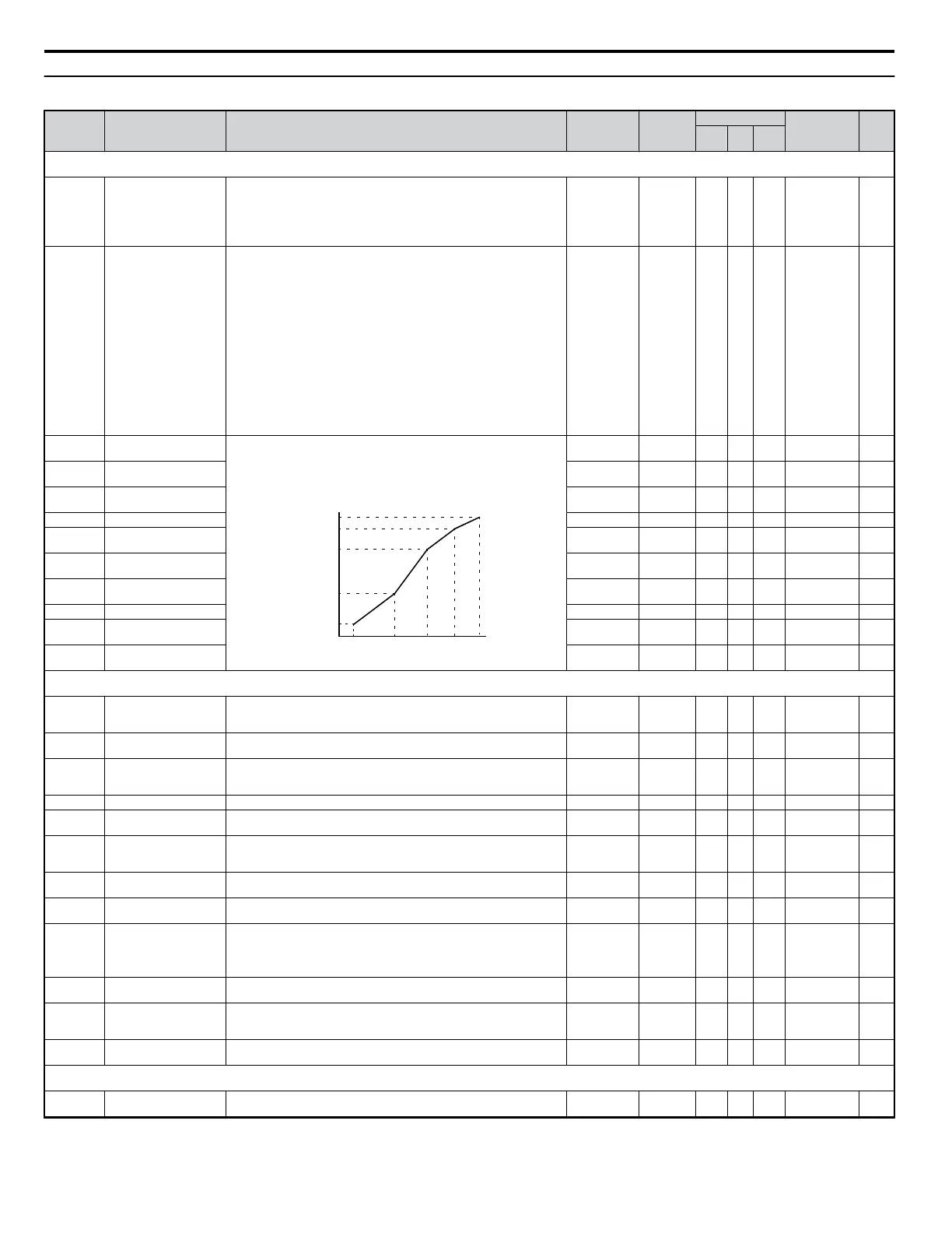
E1-04 Max Output Frequency
These parameters are only applicable when E1-03 is set to F. To set linear V/
f characteristics, set the same values for E1-07 and E1-09. In this case, the
setting for E1-08 will be disregarded. Ensure that the four frequencies are set
according to these rules:
E1-04 ≥ E1-06> E1-07 ≥ E1-09
VACrms Out(V)
Frequency (Hz)
E1-09 E1-07 E1-06 E1-11 E1-04
E1-05
E1-12
E1-13
E1-08
E1-10
40.0 to 400.0
<21>
60 Hz <10>
S S S 303 84
E1-05 <24>
Max Output Voltage 0.0 to 255.0
230 V <10>
S S S 304 84
E1-06 Base Frequency 0.0 to E1-04
60 Hz <10>
S S S 305 84
E1-07 Mid Output Frequency 0.0 to E1-04 3.0 Hz <2> A A A 306 —
E1-08 <24> Mid Output Frequency
Voltage
0.0 to 255.0
18.4 V <2>
<12>
A A A 307 —
E1-09 Minimum Output Freq. 0.0 to E1-04
1.5 Hz <2>
<10>
S S S 308 84
E1-10 <24> Minimum Output Freq.
Voltage
0.0 to 255.0
13.8 V <2>
<12>
A A A 309 —
E1-11 <26> Mid Output Frequency 2 0.0 to E1-04 0.0 Hz A A A 30A —
E1-12 <24>
<26>
Mid Output Frequency
Voltage 2
0.0 to 255.0 0.0 V A A A 30B —
E1-13 <24>
Base Voltage 0.0 to 255.0 0.0 V A S S 30C —
E2: Motor Parameters
Use E2 parameters to set motor-related data.
E2-01 Motor Rated Current
Sets the motor nameplate full load current in amperes (A).
Automatically set during Auto-Tuning.
10 to 200% of
drive rated
current <27>
<57> S S − 30E 87
E2-02 Motor Rated Slip
Sets the motor rated slip in Hertz (Hz).
Automatically set during rotational Auto-Tuning.
0.00 to 20.00 <57> A A − 30F —
E2-03 Motor No-Load Current
Sets the magnetizing current of the motor as a percentage of the motor rated
current (E2-01).
Automatically set during rotational Auto-Tuning.
0 to less than
E2-01
<57> A A − 310 —
E2-04 Number of Motor Poles Sets the number of motor poles. Automatically set during Auto-Tuning. 2 to 48 4 poles A A − 311 —
E2-05
Motor Line-to-Line
Resistance
Sets the phase-to-phase motor resistance in ohms.
Automatically set during Auto-Tuning.
0.000 to 65.000
<37>
<57> A A − 312 —
E2-06 Motor Leakage Inductance
Sets the voltage drop due to motor leakage inductance as a percentage of motor
rated voltage.
Automatically set during Auto-Tuning.
0.0 to 40.0 <57> A A − 313 —
E2-07
Motor Iron-Core
Saturation Coefficient 1
Sets the motor iron saturation coefficient at 75% of magnetic flux.
Automatically set during Auto-Tuning.
E2-07 to 0.50 0.50 − A − 314 —
E2-08
Motor Iron-Core
Saturation Coefficient 2
Sets the motor iron saturation coefficient at 75% of magnetic flux.
Automatically set during Auto-Tuning.
[E2-07] to 0.75 0.75 − A − 315 —
E2-09 Motor Mechanical Loss
Sets the motor mechanical loss as a percentage of motor rated power (kW).
Adjust in the following circumstances:
• When there is a large amount of torque loss due to motor bearing friction.
• When there is a large amount of torque loss.
0.0 to 10.0 0.0% − A − 316 —
E2-10
Motor Iron Loss for Torque
Compensation
Sets the motor iron loss in watts (W). 0 to 65535 <57> A − − 317 —
E2-11 Motor Rated Output
Sets the motor rated power in kilowatts (kW). Automatically set during
Auto-Tuning.
(1HP = 0.746 kW).
0.00 to 650.00
0.40 kW
<12>
S S − 318 85
E2-12
Motor Iron-Core
Saturation Coefficient 3
Set to the motor iron saturation coefficient at 130% of magnetic flux.
Automatically set during rotational Auto-Tuning.
1.30 to 5.00 1.30 − A − 328 —
E3: Motor 2 V/f Characteristics
Use E3 parameters to set the V/f pattern for a second motor.
E3-01 Motor 2 Control Method
0: V/f Control
2: Open Loop Vector (OLV)
0 or 2 0 A A − 319 —
B.2 Parameter Table
302
YASKAWA ELECTRIC SIEP C710606 18A YASKAWA AC Drive – V1000 Technical Manual (Preliminary)

 Loading...


