6.5 Alarm Detection
Alarms are drive protection functions that do not operate the fault contact. The drive will return to original status when the cause of the alarm has been
removed.
During an alarm condition, the Digital Operator display flashes and an alarm output is generated at the multi-function outputs (H2-01 to H2-03), if
programmed.
Investigate the cause of the alarm and refer to
Table 6.9 for the appropriate action.
u
Alarm Codes, Causes, and Possible Solutions
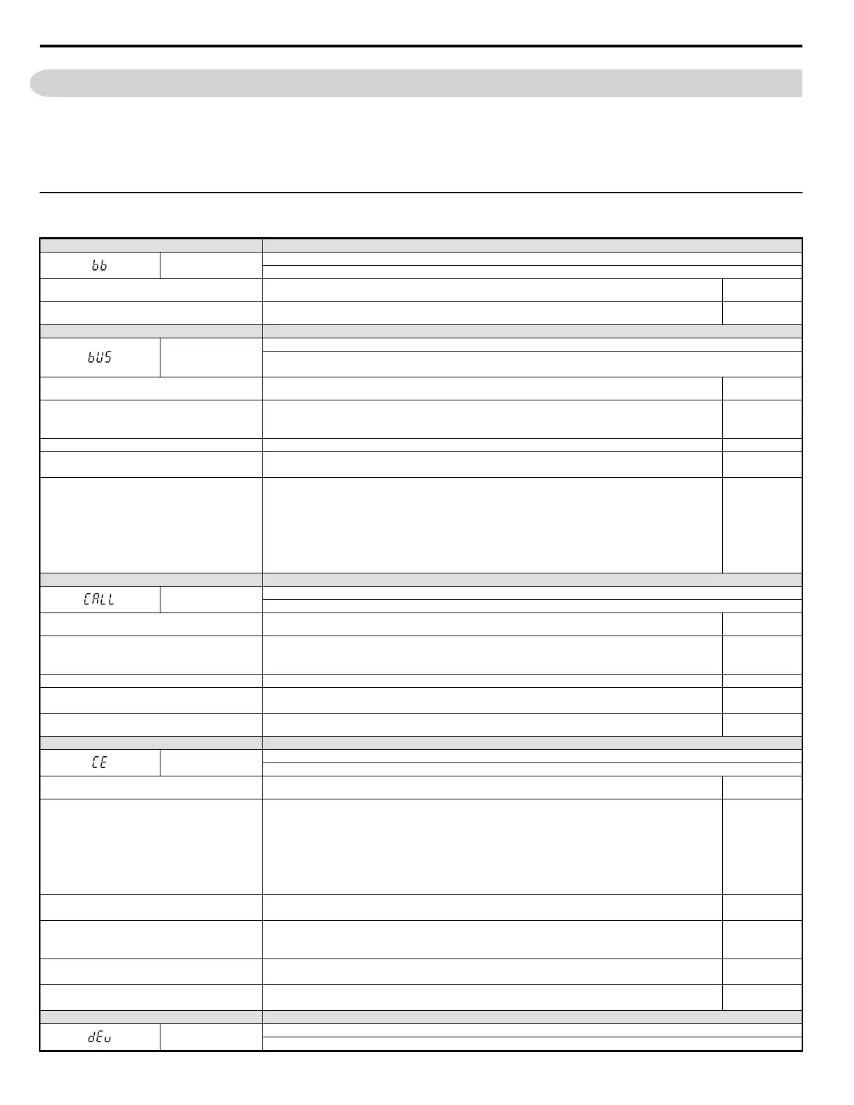
Table 6.9 Alarm Codes, Causes, and Possible Solutions
LED Operator Display Minor Fault Name
bb
Baseblock
Drive output interrupted as indicated by an external baseblock signal.
Cause Possible Solutions
Minor Fault
(H2-
oo = 10)
External baseblock signal entered via multi-function
input terminal (S1 to S7).
Check external sequence and baseblock signal input timing. No output
LED Operator Display Minor Fault Name
bUS
Option Communication Error
• After initial communication was established, the connection was lost.
• Assign a run command frequency reference to the option card.
Cause Possible Solutions
Minor Fault
(H2-
oo = 10)
Connection is broken or master controller stopped
communicating.
• Check for faulty wiring.
• Correct the wiring.
• Repair ground wiring or disconnected cables.
YES
Option card is damaged. If there are no problems with the wiring and the fault continues to occur, replace the option card. YES
The option card is not properly connected to the drive.
• The connector pins on the option card are not properly lined up with the connector pins on the drive.
• Reinstall the option card.
YES
A data error occurred due to noise.
• Check options available to minimize the effects of noise.
• Take steps to counteract noise in the control circuit wiring, main circuit lines and ground wiring.
• Try to reduce noise on the controller side.
• Use surge absorbers on magnetic contactors or other equipment causing the disturbance.
• Use cables recommended by Yaskawa, or another type of shielded line. The shield should be grounded on the
controller side or on the drive input power side.
• All wiring for communications devices should be separated from drive input power lines. Install a noise filter to
the input side of the drive input power.
YES
LED Operator Display Minor Fault Name
CALL
Serial Communication Transmission Error
Communication has not yet been established.
Cause Possible Solutions
Minor Fault
(H2-
oo = 10)
Communications wiring is faulty, there is a short circuit,
or something is not connected properly.
• Check for wiring errors.
• Correct the wiring.
• Remove and ground shorts and reconnect loose wires.
YES
Programming error on the master side. Check communications at start-up and correct programming errors. YES
Communications circuitry is damaged.
• Perform a self-diagnostics check.
• Replace the drive if the fault continues to occurs.
YES
Terminal resistance setting is incorrect.
The terminal slave drive must have the internal terminal resistance switch set correctly. Place DIP switch S2 to the
ON position.
YES
LED Operator Display Minor Fault Name
CE
MEMOBUS/Modbus Communication Error
Control data was not received correctly for two seconds.
Cause Possible Solutions
Minor Fault
(H2-
oo = 10)
A data error occurred due to noise.
• Check options available to minimize the effects of noise.
• Counteract noise in the control circuit wiring, main circuit lines and ground wiring.
• Reduce noise on the controller side.
• Use surge absorbers on magnetic contactors or other equipment causing the disturbance.
• Use cables recommended by Yaskawa or another type of shielded line. The shield should be grounded on the
controller side or on the drive input power side.
• Separate all wiring for communications devices from drive input power lines. Install a noise filter to the input side
of the drive input power.
YES
Communication protocol is incompatible.
• Check the H5 parameter settings as well as the protocol setting in the controller.
• Ensure settings are compatible.
YES
The CE detection time (H5-09) is set shorter than the time
required for a communication cycle to take place.
• Check the PLC.
• Change the software settings in the PLC.
• Set a longer CE detection time (H5-09).
YES
Incompatible PLC software settings or there is a hardware
problem.
• Check the PLC.
• Remove the cause of the error on the controller side.
YES
Communications cable is disconnected or damaged.
• Check the connector for a signal through the cable.
• Replace the communications cable.
YES
LED Operator Display Minor Fault Name
dEv
Speed Deviation (for Simple V/f with PG)
According to the pulse input (RP), the speed deviation is greater than the setting in F1-10 for a time longer than the setting in F1-11.
6.5 Alarm Detection
238
YASKAWA ELECTRIC SIEP C710606 18A YASKAWA AC Drive – V1000 Technical Manual (Preliminary)

 Loading...


