No. Name Description Range Def.
Control
Mode
Addr.
Hex
Pg.
V/f
OL
V
PM
b6: Dwell Function
Use b6 parameters to configure dwell function operation.
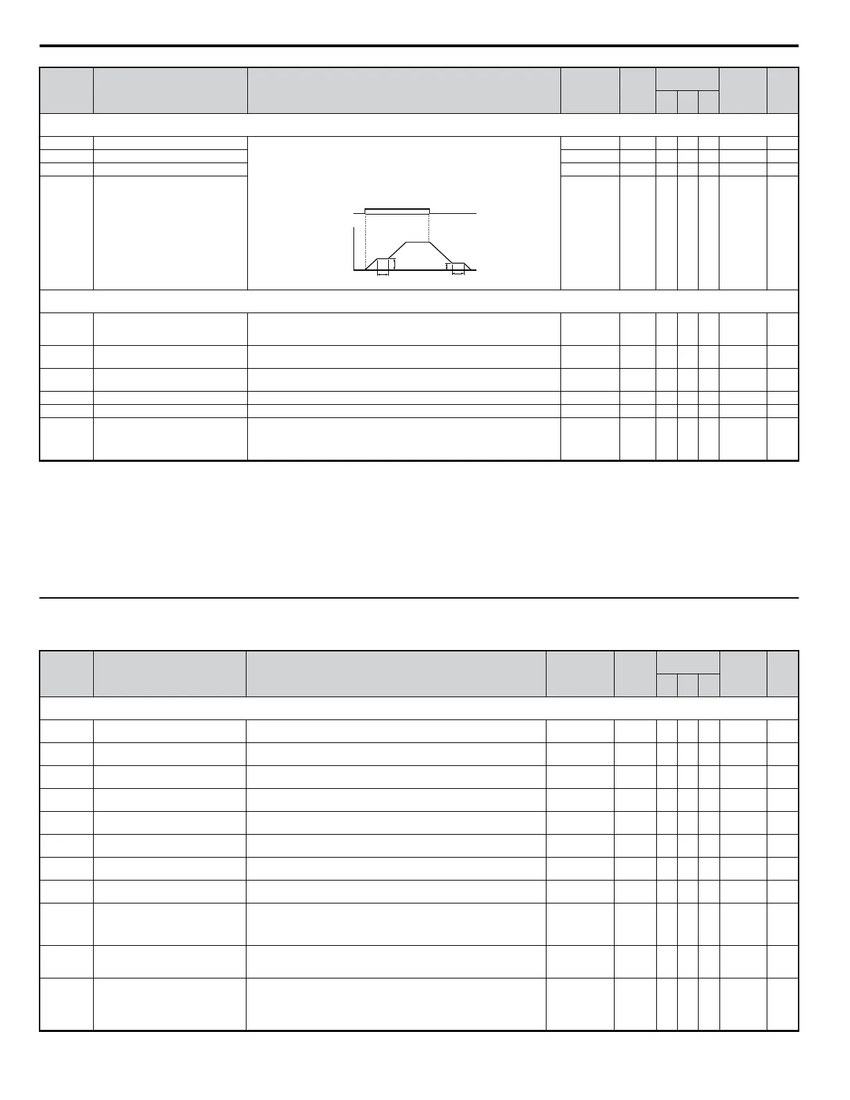
b6-01 Dwell Reference at Start The Dwell function is used to temporarily hold the frequency when driving a
motor with a heavy load.
Parameters b6-01 and b6-02 set the frequency to hold and the time to maintain
that frequency at start.
Parameters b6-03 and b6-04 set the frequency to hold and the time to maintain
that frequency at stop.
Output
Frequency
b6–02
OFF
ON
b6–01 b6–03
b6–04
Time
Run command
0.0 to 400.0 0.0 Hz A A A 1B6 —
b6-02 Dwell Time at Start 0.0 to 10.0 0.0 s A A A 1B7 —
b6-03 Dwell Frequency at Stop 0.0 to 400.0 0.0 Hz A A A 1B8 —
b6-04 Dwell Time at Stop 0.0 to 10.0 0.0 s A A A 1B9 —
b8: Energy Saving
Use b8 parameters to configure the energy saving/conservation drive function.
b8-01 Energy Saving Control Selection
Selects the Energy Savings function.
0: Disabled
1: Enabled (set b8-04)
0, 1 0 A A − 1CC —
b8-02 <22>
Energy Saving Gain Sets energy savings control gain when in Open Loop Vector (OLV) control mode. 0.0 to 10.0 0.7 − A − 1CD —
b8-03 <22> Energy Saving Control Filter Time
Constant
Sets energy saving control filter time constant when in Open Loop Vector control. 0.00 to 10.00 0.50 − A − 1CE —
b8-04 Energy Saving Coefficient Value Sets the Energy Saving coefficient and is used to fine adjustments in V/f Control. 0.0 to 655.00 <57> A − − 1CF —
b8-05 Power Detection Filter Time Sets a filter time for the Power Detection used by Energy Savings in V/f Control. 0 to 2000 20 ms A − − 1D0 —
b8-06 Search Operation Voltage Limit
Sets the limit for the voltage search operation performed by Energy Savings in
V/f Control.
Set as a percentage of the motor base voltage.
Disabled when set to 0%.
0 to 100 0% A − − 1D1 —
<1> Default setting value is dependent on parameter A1-02, Control Method Selection. The value shown is for A1-02 = 2-OLV control.
<2> Default setting value is dependent on parameter A1-02, Control Method Selection. The value shown is for A1-02 = 0-V/f Control.
<5> Default setting is dependent on parameter b5-20, PID Setpoint Scaling.
<12> Default setting value is dependent on parameter o2-04, Drive/kVA Selection.
<14> Default setting value is dependent on parameter o2-09, Initialization Spec. Selection.
<22> Parameter can be changed during run.
<32> A coasting motor may require a braking resistor circuit to bring the motor to a stop in the required time.
<33> Increase the setting value in increments of 0.1 when estimating the minimum output frequency for a motor coasting at high speed while attempting Speed-Estimation Type Speed Search.
<34> Increase this value if an OV overvoltage fault occurs when performing Speed Search at start.
<57> Default setting value is dependent on parameter o2-04, Drive/kVA Selection and C6-01, Drive Duty Selection.
u
C: Tuning
C parameters are used to adjust the acceleration and deceleration times, S-curves, slip- and torque compensation functions and carrier frequency selections.
No. Name Description Range Def.
Control
Mode
Addr.
Hex
Pg.
V/f
OL
V
PM
C1: Acceleration and Deceleration Times
Use C1 parameters to configure motor acceleration and deceleration.
C1-01 <22>
Acceleration Time 1 Sets the time to accelerate from 0 to maximum frequency.
0.0 to 6000.0
<6>
10.0 s S S S 200 81
C1-02 <22>
Deceleration Time 1 Sets the time to decelerate from maximum frequency to 0.
0.0 to 6000.0
<6>
10.0 s S S S 201 81
C1-03 <22>
Acceleration Time 2
Sets the time to accelerate from 0 to maximum frequency when Accel/Decel
times 2 are selected by a digital input.
0.0 to 6000.0
<6>
10.0 s A A A 202 —
C1-04 <22>
Deceleration Time 2
Sets the time to decelerate from maximum frequency to 0 when Accel/Decel
times 2 are selected by a digital input.
0.0 to 6000.0
<6>
10.0 s A A A 203 —
C1-05 <22> Acceleration Time 3 (Motor 2 Accel
Time 1)
Sets the time to accelerate from 0 to maximum frequency when Accel/Decel
times 3 are selected by a digital input.
0.0 to 6000.0
<6>
10.0 s A A A 204 —
C1-06 <22> Deceleration Time 3 (Motor 2 Decel
Time 1)
Sets the time to decelerate from maximum frequency to 0 when Accel/Decel
times 3 are selected by a digital input.
0.0 to 6000.0
<6>
10.0 s A A A 205 —
C1-07 <22>
Acceleration Time 4 (Motor 2 Accel
Time 2)
Sets the time to accelerate from 0 to maximum frequency when Accel/Decel
times 4 are selected by a digital input.
0.0 to 6000.0
<6>
10.0 s A A A 206 —
C1-08
Deceleration Time 4 (Motor 2 Decel
Time 2)
Sets the time to decelerate from maximum frequency to 0 when Accel/Decel
times 4 are selected by a digital input.
0.0 to 6000.0
<6>
10.0 s A A A 207 —
C1-09 Fast-Stop Time
Sets the time to decelerate from maximum frequency to 0 for the multi-
function input fast-stop function.
Note: This parameter is also used by selecting “Fast-Stop” as a Stop Method
when a fault is detected.
0.0 to 6000.0
<6>
10.0 s A A A 208 —
C1-10 Accel/Decel Time Setting Units
Sets the resolution of C1-01 to C1-09.
0: 0.01 s (0.00 to 600.00 s)
1: 0.1 s (0.0 to 6000.0 s)
0, 1 1 A A A 209 —
C1-11
Accel/Decel Time Switching
Frequency
Sets the frequency for automatic acceleration/deceleration switching.
Below set frequency: Accel/Decel Time 4
Above set frequency: Accel/Decel Time 1
The multi-function input “Accel/Decel Time 1” or “Accel/Decel Time 2” take
priority.
0.0 to 400.0 Hz 0.0 Hz A A A 20A —
B.2 Parameter Table
298
YASKAWA ELECTRIC SIEP C710606 18A YASKAWA AC Drive – V1000 Technical Manual (Preliminary)

 Loading...


