No. Name Description Range Def.
Control
Mode
Addr.
Hex
Pg.
V/f
OL
V
PM
C2: S-Curve Characteristics
Use C2 parameters to configure S-curve operation.
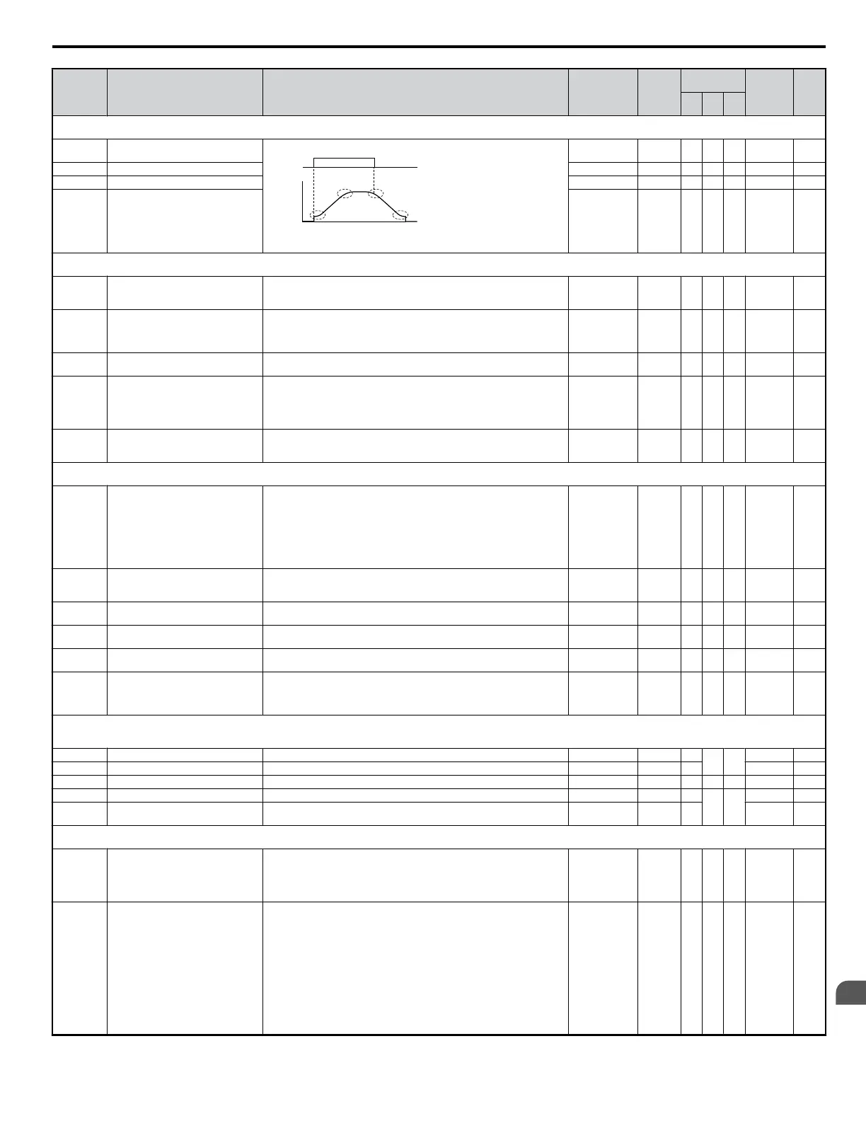
C2-01 S-Curve Characteristic at Accel Start
The S-curve can be controlled in the four points shown below.
time
run
command
output
frequency
C2-01 C2-04
C2-02 C2-03
ON
OFF
S-curve is used to further soften the starting and stopping ramp. The longer
the S-curve time, the softer the starting and stopping ramp.
0.00 to 10.00
0.20 s
<2>
A A A 20B —
C2-02 S-Curve Characteristic at Accel End 0.00 to 10.0 0.20 s A A A 20C —
C2-03 S-Curve Characteristic at Decel Start 0.00 to 10.0 0.20 s A A A 20D —
C2-04 S-Curve Characteristic at Decel End 0.00 to 10.0 0.00 s A A A 20E —
C3: Slip Compensation
Use C3 parameters to configure the slip compensation function.
C3-01 <22> Slip Compensation Gain
Sets the slip compensation gain. Decides for what amount the output
frequency is boosted in order to compensate the slip.
Note: Adjustment is not normally required.
0.0 to 2.5 0.0 <2> A A − 20F —
C3-02
Slip Compensation Primary Delay
Time
Adjusts the slip compensation function delay time.
Decrease the setting when the slip compensation response is too slow, increase
it when the speed is not stable.
Disabled when Simple V/f Control with PG (H6-01 = 3) is used.
0 to 10000
2000 ms
<2>
A A − 210 —
C3-03 Slip Compensation Limit
Sets the slip compensation upper limit. Set as a percentage of motor rated slip
(E2-02). Disabled when Simple V/f Control with PG (H6-01 = 3) is used.
0 to 250 200% A A − 211 —
C3-04
Slip Compensation Selection during
Regeneration
Selects slip compensation during regenerative operation.
0: Disabled
1: Enabled
Using the Slip Compensation function during regeneration may require a
braking option to handle momentary increasing regenerative energy.
0, 1 0 A A − 212 —
C3-05
Output Voltage Limit Operation
Selection
Selects if the motor magnetic flux is reduced during output voltage saturation.
0: Disabled
1: Enabled
0, 1 0 <2> − A − 213 —
C4: Torque Compensation
Use C4 parameters to configure Torque Compensation function.
C4-01 <23> Torque Compensation Gain
V/f control: Sets the gain for the automatic torque (voltage) boost function
and helps to produce better starting torque.
Increase this setting when using a long motor cable or when the motor is
significantly smaller than the drive capacity.
Decrease this setting when motor oscillation occurs. Set the value so that the
current at low speed does not exceeds the drives rated current.
Open Loop Vector: Sets the torque compensation function gain. Normally no
change is required.
0.00 to 2.50 1.00 A A A 215 —
C4-02
Torque Compensation Primary Delay
Time
Sets the torque compensation filter time.
Increase this setting when motor oscillation occurs.
Reduce the setting if there is not enough response from the motor.
0 to 60000
200 ms
<1>
A A A 216 —
C4-03
Torque Compensation at Forward
Start
Sets torque compensation at forward start as a percentage of motor torque. 0.0 to 200.0 0.0% − A − 217 —
C4-04
Torque Compensation at Reverse
Start
Sets torque compensation at reverse start as a percentage of motor torque. -200.0 to 0.0 0.0% − A − 218 —
C4-05 Torque Compensation Time Constant
Sets the time constant for torque compensation at forward start and reverse
start (C4-03 and C4-04). The filter is disabled if the time is set to 4 ms or less.
0 to 200 10 ms – A – 219 —
C4-06
Torque Compensation Primary Delay
Time 2
Sets the torque compensation time 2. When an OV fault occurs with sudden
load changes or at the and of an acceleration, increase the setting.
Note: Adjustment is not normally required. If adjusted then AFR time 2
(n2-03) should be adjusted too.
0 to 10000 150 ms – A – 21AH —
C5: Speed Control (ASR)
Use C5 parameters to configure the Automatic Speed Regulator (ASR).
C5 parameters are available only when using V/f with Simple PG (H6-01 = 3).
C5-01 <22> ASR Proportional Gain 1 Sets the proportional gain of the speed control loop (ASR). 0.00 to 300.00 0.20 A
– –
21B —
C5-02 <22> ASR Integral Time 1 Sets the integral time of the speed control loop (ASR). 0.000 to 10.000 0.200 s A 21C —
C5-03 <22> ASR Proportional Gain 2 Sets the speed control gain 2 of the speed control loop (ASR). 0.00 to 300.00 0.02 A − − 21D —
C5-04 <22> ASR Integral Time 2 Sets the integral time 2 of the speed control loop (ASR). 0.000 to 10.000 0.050 s A
– –
21E —
C5-05 <22> ASR Limit
Sets the upper limit for the speed control loop (ASR) as a percentage of the
maximum output frequency (E1-04).
0.0 to 20.0 5.0% A 21F —
C6: Carrier Frequency
Use C6 parameters to configure the carrier frequency drive settings.
C6-01 Normal/Heavy Duty Selection
Selects the load rating for the drive.
0: Heavy Duty (HD) for constant torque applications.
1: Normal Duty (ND) for variable torque applications.
This setting affects the Rated output current and overload tolerance of the
drive.
0, 1 1 S S S 223 82
C6-02 Carrier Frequency Selection
Selects the carrier frequency
1 : 2.0 kHz
2 : 5.0 kHz
3 : 8.0 kHz
4 : 10.0 kHz
5 : 12.5 kHz
6 : 15.0 kHz
7 : Swing PWM1 (Audible sound 1)
8 : Swing PWM2 (Audible sound 2)
9 : Swing PWM3 (Audible sound 3)
A : Swing PWM4 (Audible sound 4)
B to E: No setting possible
F : User defined (determined by C6-03 through C6-05)
1 to F <3> S S S 224 82
B.2 Parameter Table
YASKAWA ELECTRIC SIEP C710606 18A YASKAWA AC Drive – V1000 Technical Manual (Preliminary)
299
B
Parameter List

 Loading...


