C.10 Self-Diagnostics
The drive has a built-in self-diagnosing function of the serial communication interface circuits. To perform the self-diagnosis function use the following
procedure.
1. Turn on the power to the drive.
2. Set terminal S7 for the communications test mode (H1-07 = 67).
3. Turn off the power to the drive.
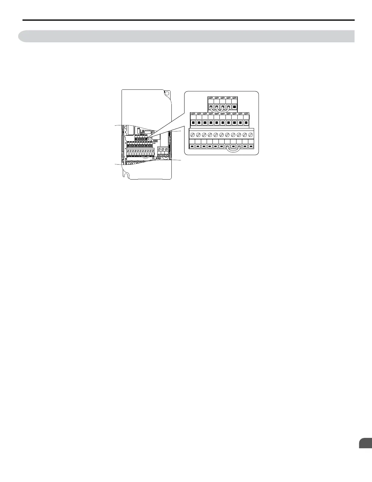
4. With the power off, wire the drive as shown in the illustration below.
S1 S2 S3 S4 S5 S6 S7 HC SC H1 RP
R+
R-
S+ S- IG
P1 P2 PC A1 A2 +V AC AM AC MP
MCMBMA
S1 S2 S3 S4 S5 S6 S7 HC SC H1 RP
R+ R- S+ S- IG
P1 P2 PC A1 A2 +V AC AM AC MP
Figure C.5 Terminal Connections for Communication Self-Diagnostics
5. The last slave in the series should have DIP switch 2 placed to the ON position in order to enable terminal resistance.
6. Turn the power to the drive back on. The DIP switch setting takes affect after the drive is turned on again.
During normal operation, the drive will display PASS. This indicates that the communications test mode is operating normally. When a fault occurs, the
drive will display CE on the keypad screen. Once the output contact closes, the “Drive Ready” signal will open.
C.10 Self-Diagnostics
YASKAWA ELECTRIC SIEP C710606 18A YASKAWA AC Drive – V1000 Technical Manual (Preliminary)
343
C
MEMOBUS/Modbus
Communications

 Loading...


