5.7 H: Terminal Functions
H parameters are used to assign functions to the external terminals.
u
H1: Multi-Function Contact Inputs
n
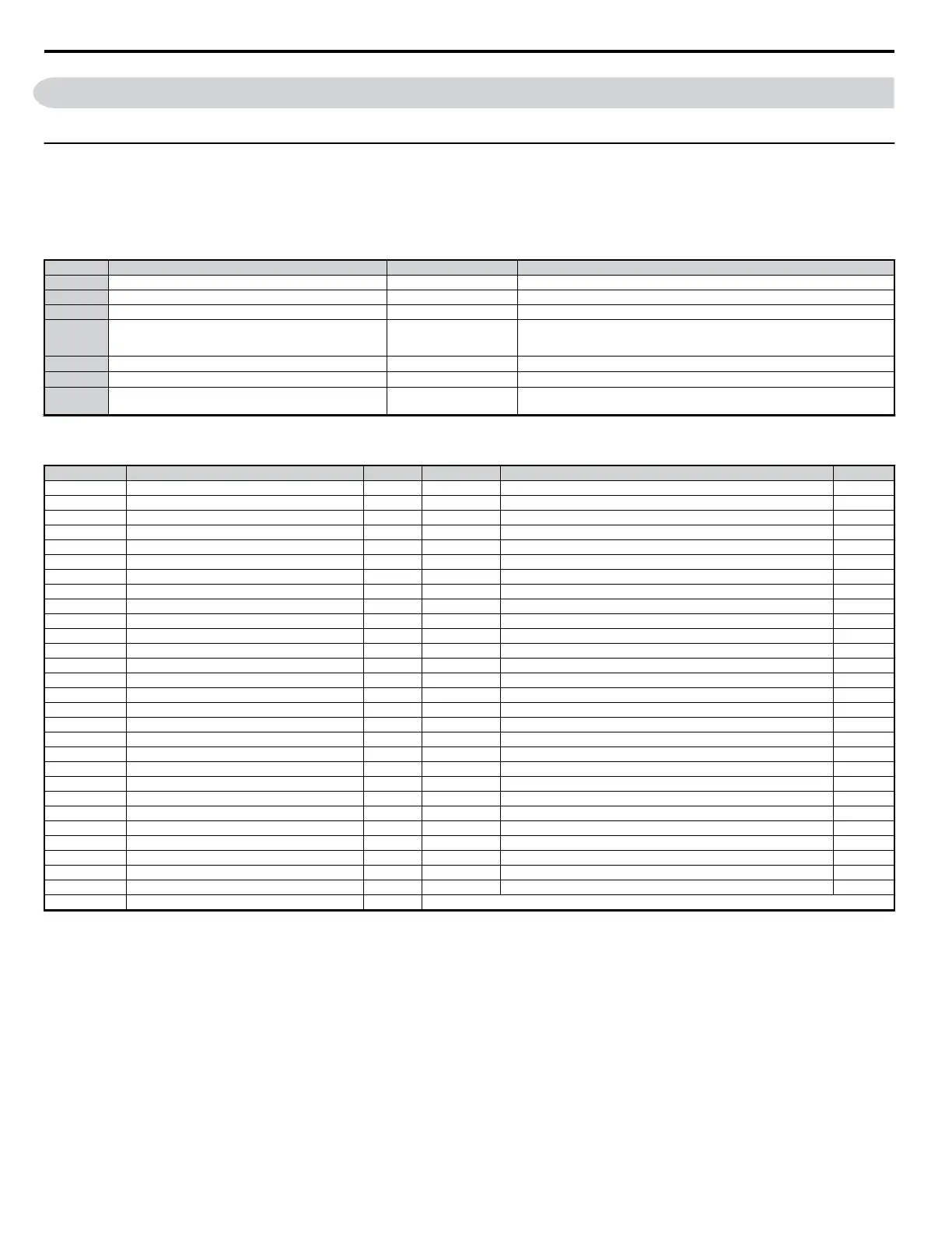
H1-01 to H1-07: Functions for Terminals S1 to S7
These parameters assign functions to the seven multi-function contact inputs located at terminals S1 through S7. Settings 0 to 9F determine the type of
input for each terminal.
Note: If not using an input terminal or if using the through-mode, set that terminal to “F”.
No. Parameter Name Setting Range Default
H1-01 Multi-Function Digital Input Terminal S1 Function Selection 1 to 9F 40: Forward Run Command (2-wire sequence)
H1-02 Multi-Function Digital Input Terminal S2 Function Selection 1 to 9F 41: Reverse Run Command (2-wire sequence)
H1-03 Multi-Function Digital Input Terminal S3 Function Selection 0 to 9F 24: External Fault (user selection possible)
H1-04 Multi-Function Digital Input Terminal S4 Function Selection 0 to 9F
14: Fault Reset
Closed: Allows the drive to run again after the fault is cleared and the run command is
removed
H1-05 Multi-Function Digital Input Terminal S5 Function Selection 0 to 9F
3 (0)
*
: Multi-Step Speed Reference 1
H1-06 Multi-Function Digital Input Terminal S6 Function Selection 0 to 9F
4 (3)
*
: Multi-Step Speed Reference 2
H1-07 Multi-Function Digital Input Terminal S7 Function Selection 0 to 9F
6 (4)
*
: Jog Reference Selection
Takes priority over other multi-step speed references 1 through 16
*Number appearing in parenthesis is the default value after performing a 3-wire initialization.
Table 5.15 Multi-Function Contact Input Settings
Setting Function Page Setting Function Page
0 3-Wire Sequence − 4 Multi-Step Speed Reference 2 −
1 LOCAL/REMOTE Selection − 5 Multi-Step Speed Reference 2 −
2 Option/Drive Selection − 6 Jog Reference Selection −
3 Multi-Step Speed Reference 1 − 7 Accel/Decel Time 1 −
8 Baseblock Command (N.O.) − 40 Forward Run Command (2-wire sequence) −
9 Baseblock Command (N.C.) − 41 Reverse Run Command (2-wire sequence) −
A Accel/Decel Ramp Hold − 42 Run Command (2-wire sequence 2) −
B Drive Overheat Alarm (OH2) − 43 FWD/REV Command (2-wire sequence 2) −
C Terminal A2 Enable − 44 Offset Frequency 1 Addition −
F Not used − 45 Offset Frequency 2 Addition −
10 Up Command − 46 Offset Frequency 3 Addition −
11 Down Command − 60 DC Injection Braking Command −
12 Forward Jog − 61 External Search Command 1 −
13 Reverse Jog − 62 External Search Command 2 −
14 Fault Reset − 65 KEB Ride-Thru (N.C.) −
15 Fast-Stop (N.O.) − 66 KEB Ride-Thru (N.O.) −
16 Motor 2 Selection − 67 Communications Test Mode −
17 Fast-stop (N.C.) − 68 High-Slip Braking −
18 Timer Function − 6A Drive Enable −
19 PID Disable − 75 Up 2 Command −
1A Accel/Decel Time Selection 2 − 76 Down 2 Command −
1B Program Lockout − 7A KEB Ride-Thru 2 (N.C.) −
1E Reference Sample Hold − 7B KEB Ride-Thru 2 (N.O.) −
20 to 2F External Fault − 7C Short-Circuit Braking (N.O.) −
30 PID Integral Reset − 7D Short-Circuit Braking (N.C.) −
31 PID Integral Hold − 7E Forward/Reverse Detection (Simple PG in V/f) −
32 Multi-Step Speed Reference 4 − 90 to 96 DriveWorksEZ Digital Input 1 to 7 −
34 PID Soft Starter − 9F DriveWorksEZ Digital Input 9F −
35 PID Input Switch −
Detailed Description
Setting 0: 3-Wire Sequence
When one of the digital inputs (S3 to S7) is programmed for 3-wire control, that input becomes a forward/reverse directional input. Whenever the input
is open, the drive will be set for forward rotation of the motor shaft. If the input it closed, then the motor shaft will rotate in the reverse direction whenever
a there is a run command entered.
Note: The run and stop commands are allotted to terminals S1 and S2.
5.7 H: Terminal Functions
160
YASKAWA ELECTRIC SIEP C710606 18A YASKAWA AC Drive – V1000 Technical Manual (Preliminary)

 Loading...


