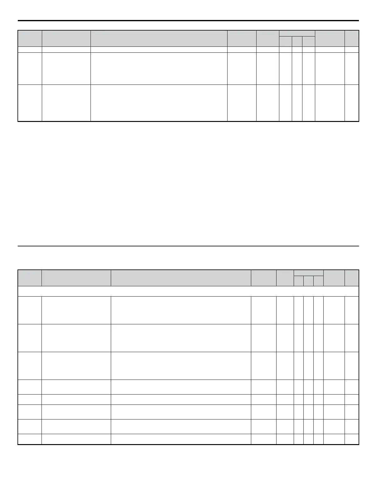
No. Name Description Range Def.
Control Mode
Addr. Hex Pg.
V/f
OL
V
PM
E5-07 <25> Motor q Axis Inductance Sets the q axis inductance in units of 0.01 mH. 0.00 to 600.00 <10> − − S 32F 325
E5-09 <25>
Motor Induction Voltage
Constant 1
Set the induced phase peak voltage in units of 0.1 mV (rad/min) [electrical
angle].
Set this parameter when using a Yaskawa SSR1 series PM motor with derate
torque, or a Yaskawa SST4 series motor with constant torque.
When setting this parameter, E5-24 should be set to 0. An alarm will be
triggered if both E5-09 and E5-24 are set to 0, or if neither parameter is set to
0.
0.0 to 2000.0 <10> − − S 331 325
E5-24 <25> Motor Induction Voltage
Parameter 2
Set the induced phase-to-phase rms voltage in units of 0.1 mV/(r/min)
[mechanical angle].Set this parameter when using a Yaskawa SMRA series
pico motor.
When setting this parameter, E5-09 should be set to 0. An alarm will be
triggered if both E5-09 and E5-24 are set to 0, or if neither parameter is set to
0.
If E5-03 (Motor Rated Current) is set to 0, however, then an alarm will not be
triggered when both E5-09 and E5-24 are set to 0.
0.0 to 2000.0 0 <10> − − S 353 325
Default setting value is dependent on parameter A1-02, Control Method Selection. The value shown is for A1-02 = 2-OLV control.
Default setting value is dependent on parameter A1-02, Control Method Selection. The value shown is for A1-02 = 0-V/f Control.
Default setting value is dependent on parameter A1-06. This setting value is 0 when A1-06 = 0, and 1 when A1-06 does not = 0.
Default setting value is dependent on parameter E5-01, Motor Code Selection.
Default setting value is dependent on parameter o2-04, Drive/kVA Selection.
Default setting value is dependent on parameter o2-04, Drive Capacity, when parameter H1-oo = 16 Motor 2 is selected as a digital input. The value shown is when o2-04 = 98 (62H) 200V
class 0.4 kW drive.
Range upper limit is dependent on parameters E5-01, Motor Code Selection, and A1-02, Control Method Selection. The value shown is for A1-02 = 5-PM OLV control.
Range upper limit is dependent on parameter E4-01 Motor 2 Rated Current.
Parameter can be changed during run.
Values shown here are for 200 V class drives. Double the value when using a 400 V class drive.
Parameter setting value is not reset to the default value during drive initialization, A1-03 = 1110, 2220, 3330.
Parameter ignored when E1-11, Motor 1 Mid Output Frequency 2, and E1-12, Motor 1 Mid Output Frequency Voltage 2, are set to 0.0.
Setting units for this parameter are determined by o2-04, Drive/kVA Selection. Less than 11 kW: 2 decimal points, 11 kW and above: 1 decimal point.
When parameter A1-02 = 5-PM OLV Control, E3-13 Motor 2 Base Voltage will be equal to T1-03, Motor Rated Voltage, after Auto-Tuning the drive
Default setting is determined by the V/f pattern selected to parameter E1-03.
Default setting changes when using OLV Control for PM motors.
Setting range becomes 0.00 to 130.00 for drives 0.2 kW and smaller.
If using a Yaskawa pico motor, the default setting is 1800 r/min.
Parameter ignored when E3-11, Motor 2 Mid Output Frequency 2, and E3-12, Motor 2 Mid Output Frequency Voltage 2, are set to 0.
Default setting depends on the control mode for motor 2 set in parameter E3-01. The given value is for V/f control.
Default setting value is dependent on parameter o2-04, Drive/kVA Selection and C6-01, Drive Duty Selection.
u
F: Options
F parameters are used to program the drive for PG feedback and to function with option cards.
No. Name Description Range Def.
Control Mode
Addr.
Hex
Pg.
V/f
OL
V
PM
F1: Simple PG V/f Parameters
Use F1 parameters to set up the drive for Simple PG V/f control. These parameters are enabled only when H6-01 = 03.
F1-02
Operation Selection at PG Open Circuit
(PGO)
Sets stopping method when a PG open circuit fault (PGO) occurs. Refer to
parameter F1-14.
0: Ramp to Stop - Decelerate to stop using the active deceleration time.
1: Coast to Stop
2: Fast-stop - Decelerate to stop using the deceleration time in C1-09.
3: Alarm only - Drive continues operation.
0 to 3 1 A − − 381 —
F1-03
Operation Selection at Overspeed
(OS)
Sets the stopping method when an overspeed (OS) fault occurs. Refer to F1-08
and F1-09.
0: Ramp to stop - Decelerate to stop using the active deceleration time.
1: Coast to stop
2: Fast - Stop - Decelerate to stop using the deceleration time in C1-09.
3: Alarm Only - Drive continues operation.
0 to 3 1 A − − 382 —
F1-04 Operation Selection at Deviation
Sets the stopping method when a speed deviation (DEV) fault occurs. Refer to
F1-10 and F1-11.
0: Ramp to stop - Decelerate to stop using the active deceleration time.
1: Coast to stop
2: Fast-stop - Decelerate to stop using the deceleration time in C1-09.
3: Alarm only - Drive continues operation.
0 to 3 3 A − − 383 —
F1-08 Overspeed Detection Level
Sets the speed feedback level which has to be exceeded for the time set in F1-09
before an OS fault will occur.
Set as a percentage of the maximum output frequency (E1-04).
0 to 120 115% A − − 387 —
F1-09 Overspeed Detection Delay Time
Sets the time in seconds for which the speed feedback has to exceed the overspeed
detection level F1-08 before an OS fault will occur.
0.0 to 2.0 1.0 A − − 388 —
F1-10
Excessive Speed Deviation Detection
Level
Sets the allowable deviation between motor speed and frequency reference before
a speed deviation fault (DEV) is triggered.
Set as a percentage of the maximum output frequency (E1-04).
0 to 50 10% A − − 389 —
F1-11
Excessive Speed Deviation Detection
Delay Time
Sets the time in seconds for which a deviation between motor speed and
frequency reference has to exceed the speed deviation detection level F1-10
before a DEV fault will occur.
0.0 to 10.0 0.5 s A − − 38A —
F1-14 PG Open-Circuit Detection Time
Sets the time for which no PG pulses must be detected before a PG Open (PGO)
fault is triggered.
0.0 to 10.0 2.0 s A − − 38D —
B.2 Parameter Table
304
YASKAWA ELECTRIC SIEP C710606 18A YASKAWA AC Drive – V1000 Technical Manual (Preliminary)

 Loading...


