B.2 Parameter Table
u
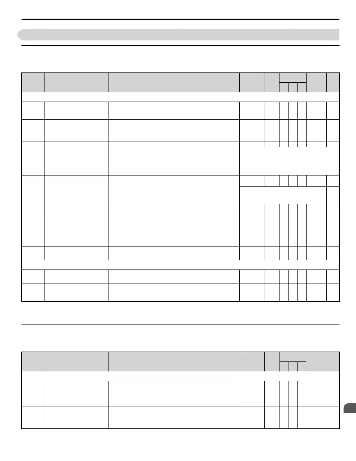
A: Initialization Parameters
The A parameter group creates the operating environment for the drive. This includes the parameter Access Level, Motor Control Method, Password,
User Parameters and more.
No. Name Description Range Def.
Control
Mode
Addr.
Hex
Pg.
V/f
OL
V
PM
A1: Initialization Parameters
Use A1 parameters to configure the basic environment for drive operation.
A1-01 <22>
<16>
Access Level Selection
Selects which parameters are accessible via the digital operator.
0: Operation only
1: User Parameters (access to a set of parameters selected by the user)
2: Advanced Access Level
0 to 2 2 A A A 101H —
A1-02 Control Method Selection
Selects the Control Method of the drive.
0: V/f Control without PG
2: Open Loop Vector (OLV)
5: PM Open Loop Vector (PM)
Note: Does not return to the default setting when the drive is initialized.
0, 2, 5 0 S S S 102 75
A1-03 Initialize Parameters
Resets all parameters to factory default settings. (Initializes the drive then returns
A1-03 to 0)
0: No Initialize
1110: User Initialize
(First set user parameter values must be stored using parameter o2-03)
2220: 2-Wire Initialization
3330: 3-Wire Initialization
5550: OPE04 Error Reset
0 to 3330 0 A A A 103 —
The following parameters are not reset when the performing
initialization:
A1-00, A1-02, A1-07, and all U2 and U3 monitors.
A1-04 Password 1
When the value set into A1-04 does not match the value set into A1-05,
parameters A1-01 thru A1-03, A1-06, and A2-01 thru A2-32 cannot be changed.
0 to 9999 0 A A A 104 —
A1-05 Password 2
0 to 9999 0 A A A 105 —
This parameter is hidden from view. To access A1-05,
first display A1-04. Then press the STOP key while
holding down the up arrow key. Parameter A1-05 will
appear.
—
A1-06 Application Preset
Sets parameters that are commonly used in certain applications to A2-01 through
A2-16 for easier access.
0: General-purpose (A2 parameters are not affected)
1: Water supply pump
2: Conveyor
3: Exhaust fan
4: HVAC fan
5: Air compressor
6: Crane (Hoist)
7: Crane (Travelling)
0 to 7 0 A A A 127 —
A1-07 DriveWorksEZ Function Selection
0: Disabled
1: Enabled
2: Multi-function input (enabled when H1-oo = 9F)
0 to 2 0 A A A —
A2: User Parameters
Use A2 parameters to program the drive.
A2-01 to
A2-32
User Parameters, 1 to 32
Parameters that were recently edited are listed here. The user can also select
parameters to appear here for quick access.
Parameters will be stored here for quick access when A1-01 = 1.
b1-01 to o2-08 -- <16> A A A 106 to 125 —
A2-33 User Parameter Automatic Selection
0: Parameters A2-01 through A2-32 are reserved for the user to create a list of
User Parameters.
1: Save history of recently viewed parameters. Recently edited parameters will
be saved to A2-17 through A2-32 for quick access.
0, 1 1 <4> A A A 126 —
<4> Default setting value is dependent on parameter A1-06. This setting value is 0 when A1-06 = 0, and 1 when A1-06 does not = 0.
<16> Default setting value is dependent on parameter A1-06, Application Selection.
<22> Parameter can be changed during run.
u
b: Application
Application parameters configure the Run Command Source, DC Injection Braking, Speed Search, Timer functions, PID control, the Dwell function,
Energy Savings and a variety of other application-related settings.
No. Name Description Range Def.
Control
Mode
Addr.
Hex
Pg.
V/f
OL
V
PM
b1: Operation Mode Selection
Use b1 parameters to configure the operation mode.
b1-01 Frequency Reference Selection 1
Selects the frequency reference input source.
0: Operator - Digital preset speed d1-01 to d1-17.
1: Terminals - Analog input terminal A1 or A2.
2: MEMOBUS/Modbus communications
3: Option PCB
4: Pulse Input (Terminal RP)
0 to 4 1 S S S 180 76
b1-02 Run Command Selection 1
Selects the run command input source.
0: Operator - RUN and STOP keys on the digital operator.
1: Digital input terminals S1 to S7
2: MEMOBUS/Modbus communications
3: Option PCB.
0 to 3 1 S S S 181 77
B.2 Parameter Table
YASKAWA ELECTRIC SIEP C710606 18A YASKAWA AC Drive – V1000 Technical Manual (Preliminary)
295
B
Parameter List

 Loading...


