EasyManuals Logo

YASKAWA V1000 Series Technical Manual

YASKAWA V1000 Series
372 pages
To Next Page IconTo Next Page
To Previous Page IconTo Previous Page
Page #270 background imageLoading...
Page #270 background image
8.3 Connecting Peripheral Devices
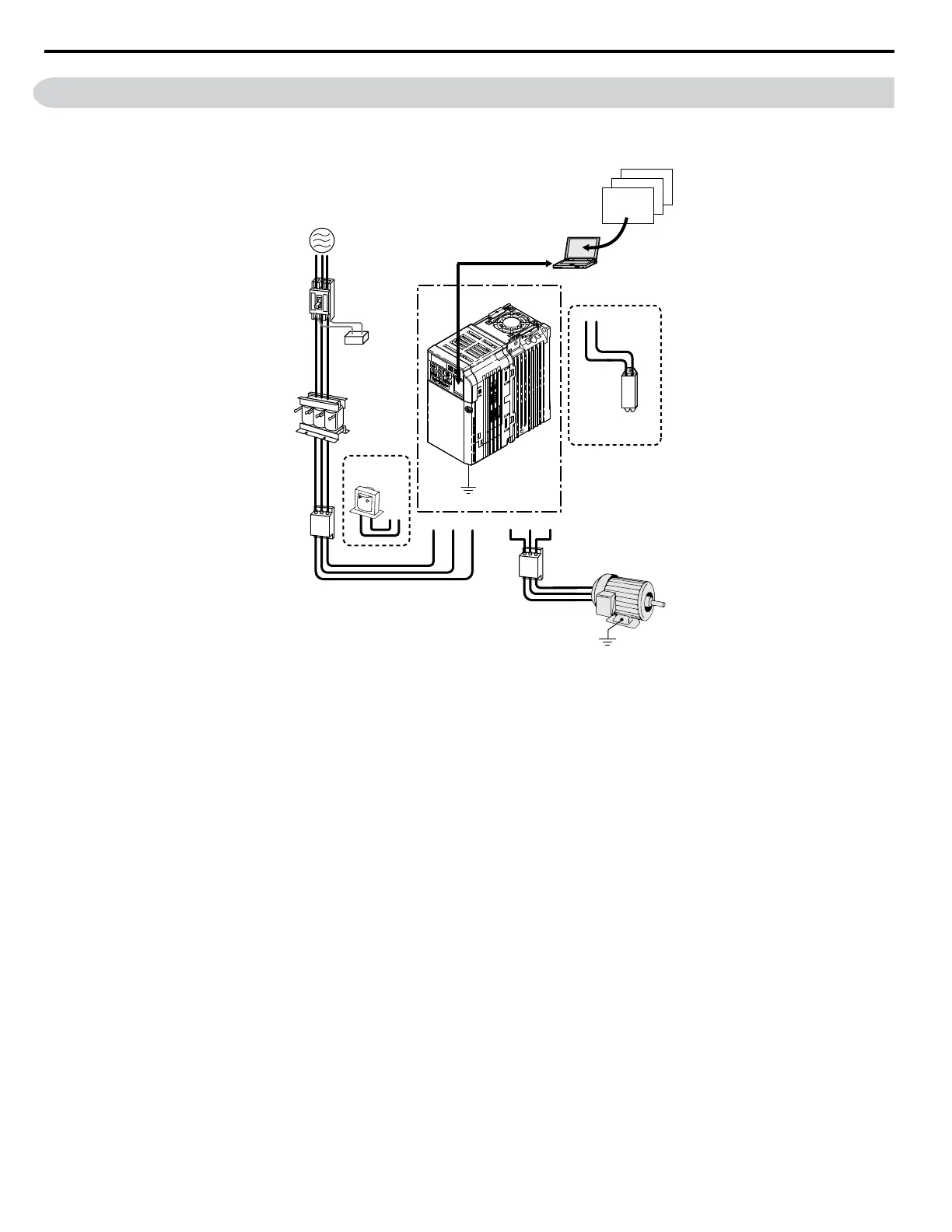
Figure 8.1 illustrates how the drive and motor connect together with various peripheral devices.
Refer to peripheral device option manual for detailed installation instructions.
Drive
Ground
PC
To serial comm port
Ground
Motor
Power
supply
Engineering software tools
U/T1 V/T2 W/T3R/L1 S/L2
+2+1
T/L3
DriveSelect
DriveWizard
DriveWorksEZ
B1 B2
Line
breaker
(MCCB)
or
Leakage
breaker
Surge
absorber
AC reactor
Input side
noise filter
DC reactor
Braking
resistor
unit
Output side
noise filter
Figure 8.1 Connecting Peripheral Devices
8.3 Connecting Peripheral Devices
270
YASKAWA ELECTRIC SIEP C710606 18A YASKAWA AC Drive – V1000 Technical Manual (Preliminary)

Table of Contents

Other manuals for YASKAWA V1000 Series

Questions and Answers:

Question and Answer IconNeed help?

Do you have a question about the YASKAWA V1000 Series and is the answer not in the manual?

YASKAWA V1000 Series Specifications

General IconGeneral
ModelV1000 Series
SeriesV1000
Output Frequency0.1 to 400 Hz
Overload Capacity150% for 60 seconds
TypeAC Drive
Control MethodV/f Control
Input Voltage200-240V, 380-480V
Output Voltage0 to Input Voltage
Power Range0.1 to 18.5 kW
Horsepower0.2 to 25 HP
Protection FeaturesOvercurrent, Overvoltage, Undervoltage, Overheating, Short Circuit, Ground Fault
Communication InterfacesModbus RTU
EnclosureIP20
Ambient Temperature-10 to +50°C
Storage Temperature-20 to +60°C
Humidity5 to 95% RH (non-condensing)
Cooling MethodFan Cooled

Related product manuals