A.4 Drive Specifications
Note: Perform rotational Auto-Tuning to obtain OLV performance specifications.
Note: For optimum performance life of the drive, install the drive in an environment that meets the environmental conditions.
Item Specification
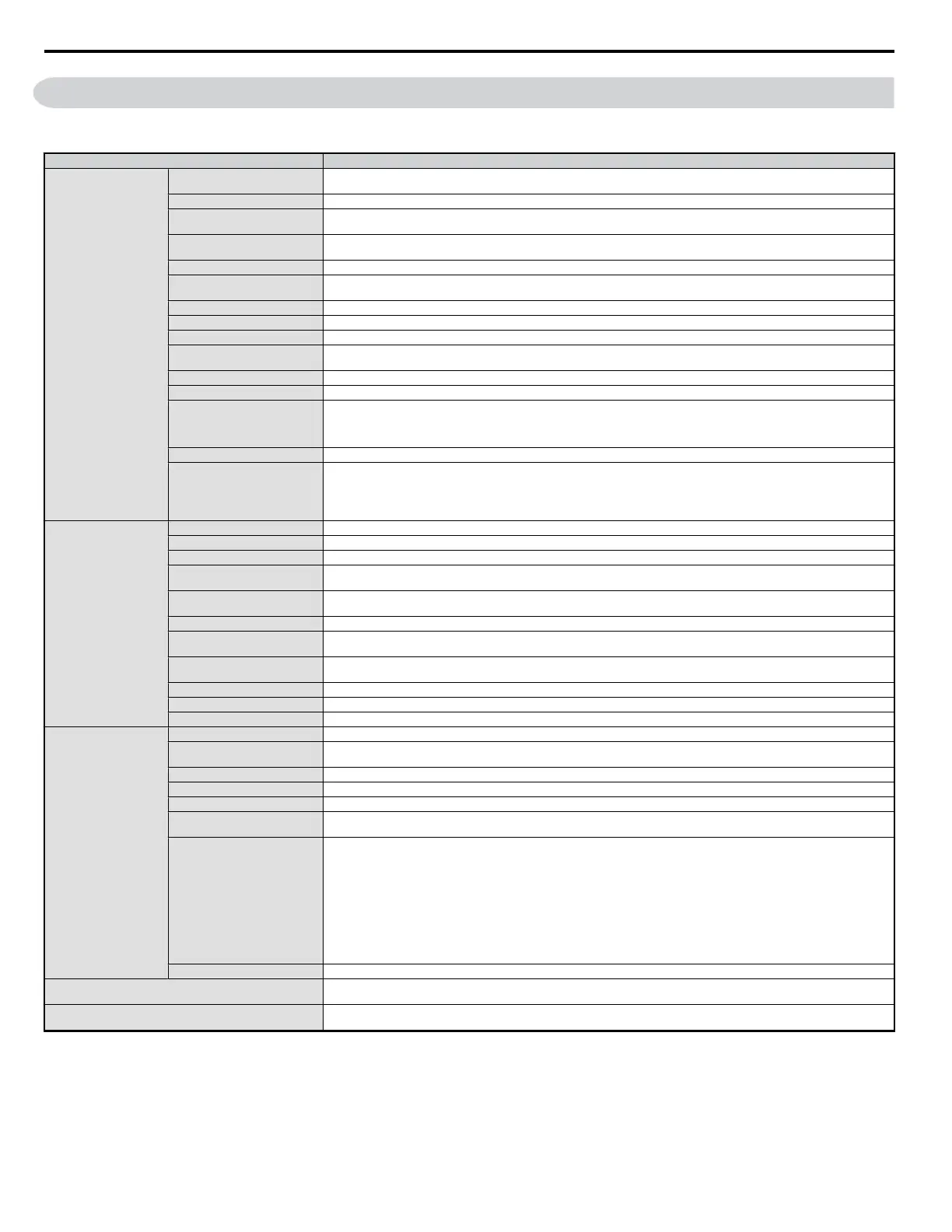
Control Characteristics
Control Method
The following control methods are available:
Open Loop Vector Control (current vector), V/f Control, and PM Open Loop Vector for (for use with SPM and IPM)
Frequency Control Range 0.01 to 400 Hz
Frequency Accuracy
Digital input: within ±0.01% of the max output frequency (-10 to +50 °C)
Analog input: within ±0.5% of the max output frequency (25°C ±10 °C)
Frequency Setting Resolution
Digital inputs: 0.01 Hz
Analog inputs: 1/1000 of maximum output frequency
Output Frequency Resolution 1/220 of maximum output frequency
Frequency Setting Signal
Main frequency reference: 0 to +10 Vdc (20 kΩ), 4 to 20 mA (250 Ω), 0 to 20 mA (250 Ω)
Main speed reference: Pulse Train Input (max 33 kHz)
Starting Torque 200%/0.5 Hz (Open Loop Vector Control, HD rating, IM of 3.7 kW or smaller), 50%/6 Hz (PM Open Loop Vector Control)
Speed Control Range 1:100 (Open Loop Vector Control), 1:40 (V/f Control), 1:10 (PM Open Loop Vector Control)
Speed Control Accuracy 0.2% in Open Loop Vector Control <1>
Speed Response
5 Hz (20 °C ±10 °C) in Open Loop Vector Control
(excludes temperature fluctuation when performing Rotational Auto-Tuning)
Torque Limit Open Loop Vector Control only. Adjustable in 4 quadrants.
Accel/Decel Time 0.00 to 6000.0 s (allows four separate settings for accel and decel)
Braking Torque
Instantaneous Average Decel Torque <2> : 0.1/0.2 kW: over 150%, 0.4/0.75 kW: over 100%, 1.5 kW: over 50%, 2.2 kW and above:
over 20%
Continuous Regen Torque: 20%,
125% with a Braking Resistor Unit <3> : (10% ED) 10 s with an internal braking resistor.
V/f Characteristics Preset V/f patterns and user-set program available.
Drive Functions
Momentary Power Loss Ride-Thru, Speed Search, Overtorque Detection, Torque Limit, Multi-Step Speed (17 steps max), Accel/
Decel Time Switch, S-Curve Accel/Decel, 3-Wire Sequence, Rotational Auto-Tuning, Stationary Auto-Tuning of Line-to-Line
Resistance, Dwell, Cooling Fan ON/OFF, Slip Compensation, Torque Compensation, Frequency Jump, Frequency Reference Upper/
Lower Limit, DC Injection Braking (start and stop), High Slip Braking, PID Control (with Slip Function), Energy Saving,
MEMOBUS/Modbus (RS-485/422 Max 115.2 kbps), Fault Reset, Parameter Copy.
Protection Functions
Motor Protection Momentary Motor overheat protection via output current sensor
Overcurrent Protection Drives stops when output exceeds 200% of the rated current (Heavy Duty)
Overload Protection A stop command will be entered after operating at 150% for 60 s (Heavy Duty) <4>
Low Voltage Protection
Drive stops when DC bus voltage falls below the levels indicated: <5>
190 V (3-phase 200 V), 160 V (single-phase 200 V), 380 V (3-phase 400 V), 350 V (3-phase 380 V)
Momentary Power Loss Ride-
Thru
3 selections available: Ridethru disabled (stops after 15 ms), time base of 0.5 s, and continue running until power is restored. <6>
Heatsink Overheat Protection Protected by thermistor
Braking Resistor Overheat
Protection
Overheat sensor for braking resistor (Optional ERF-type, 3% ED)
Stall Prevention
Stall prevention is available during acceleration, deceleration, and during run. Separate settings for each type of stall prevention
determine the current level at which stall prevention is triggered.
Cooling Fan Failure Protection Circuit protection (“fan-lock” sensor)
Ground Protection Electronic circuit protection (triggered by the same levels as momentary current protection) <7>
DC Bus Charge LED Remains lit until DC bus voltage falls below 50 V
Environment
Storage/Installation Area Indoors
Ambient Temperature
-10 to +40 °C (wall-mounted enclosure)
-10 to +50 °C (open chassis)
Humidity 95 RH% or less with no condensation
Storage Temperature -20 to +60 °C allowed for short-term transport of the product
Altitude 1000 m or less
Shock, Impact
10 to 20 Hz: 9.8 m/S 2
20 to 55 Hz: 5.9 m/S 2
Surrounding Area
Install the drive in an area free from:
• oil mist and dust
• metal shavings, oil, water or other foreign materials
• radioactive materials
• combustible materials
• harmful gases and liquids
• excessive vibration
• chlorides
• direct sunlight
Orientation Install the drive vertically to maintain maximum cooling effects
Safety Regulations and Standards
UL508C, EN954-1 Cat. 3
<>
Protective Enclosure
Open chassis (IP20)
Wall-mounted enclosure (NEMA Type 1): available as an option
A.4 Drive Specifications
286
YASKAWA ELECTRIC SIEP C710606 18A YASKAWA AC Drive – V1000 Technical Manual (Preliminary)

 Loading...


