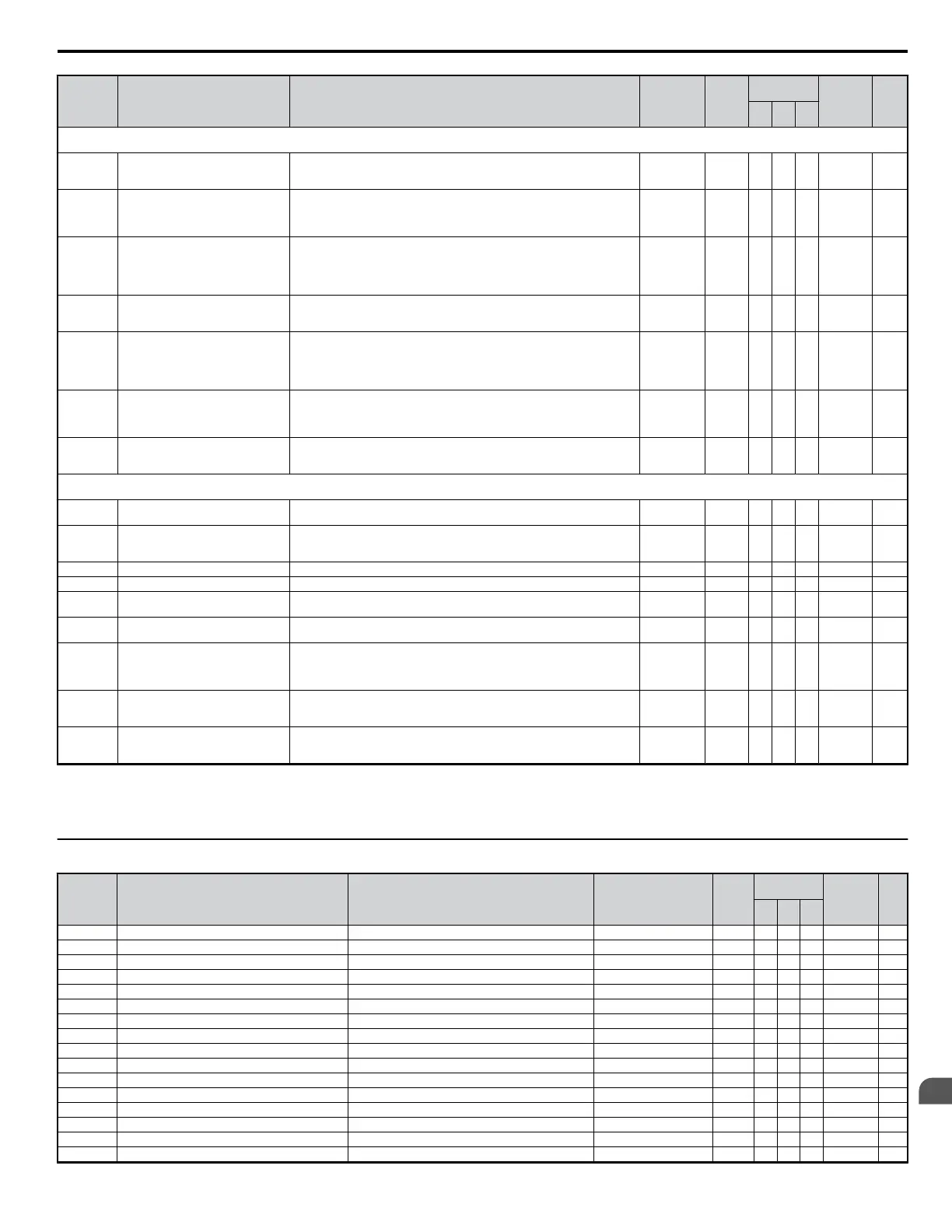
No. Name Description Range Def.
Control
Mode
Addr.
Hex
Pg.
V/f
OL
V
PM
o2: Operator Keypad Functions
Use o2 parameters to configure LED digital operator key functions.
o2-01
LOCAL/REMOTE Key Function
Selection
Enables/Disables the digital operator LOCAL/REMOTE key.
0: Disabled
1: Enabled
0, 1 1 A A A 505 —
o2-02 STOP Key Function Selection
Enables/Disables the operator panel STOP key when the drive is operated form
external sources (not operator).
0: Disabled
1: Enabled
0, 1 1 A A A 506 —
o2-03 User Parameter Default Value
Allows storing of parameter settings as a User Initialization Selection (value 1110
for A1-03). The value returns to 0 after entering 1 or 2.
0: No Change
1: Set Defaults - Saves current parameter settings as user initialization.
2: Clear All - Clears the currently saved user initialization.
0 to 2 0 A A A 507 —
o2-04 Drive/kVA Selection
Sets the kVA of the drive.
This parameter only needs to be set when installing a new control board. Do not
change for other reason.
0 to FF <12> A A A 508 —
o2-05
Frequency Reference Setting Method
Selection
Selects if the ENTER key must be pressed when inputting the frequency reference
by the operator keypad.
0: Data/Enter key must be pressed to enter a frequency reference.
1: Data/Enter key is not required. The frequency reference is adjusted by the “up”
and “down” arrow keys.
0, 1 0 A A A 509 —
o2-06
Operation Selection when Digital
Operator is Disconnected
Sets drive action when the digital operator is removed in Local mode or with
b1-02 = 0.
0: The drive will continue operation
1: The drive will trigger a fault (OPR) and the motor will coast to stop
0, 1 0 A A A 50A —
o2-07
Motor Direction at Power Up when
Using Operator
0: Forward
1: Reverse
This parameter requires that drive operation be assigned to the digital operator.
0 to 1 0 A A A 527 —
o4: Maintenance Period
Use o4 parameters to perform maintenance.
o4-01 Accumulated Operation Time Setting
Sets the starting value for the cumulative operation time of the drive in units of
10h.
0 to 9999 0 A A A 50B —
o4-02
Accumulated Operation Time
Selection
Sets this parameter to log the cumulative operation time (U4-01).
0: Logs power-on time
1: Logs operation time when the drive output is active (output operation time).
0 to 1 0 A A A 50C —
o4-03 Cooling Fan Operation Time Setting Used to resets the Cooling Fan operation time counter U1-04. 0 to 9999 0 A A A 50E —
o4-05 Capacitor Maintenance Setting Resets the capacitor maintenance time monitor U4-05. 0 to 150 0% A A A 51D —
o4-07
Inrush Prevention Relay Maintenance
Setting
Resets the Inrush Prevention Relay Maintenance monitor U4-06. 0 to 150 0% A A A 523 —
o4-09 IGBT Maintenance Setting
Resets the counter that logs the IGBTs usage time. Refer to U4-07 (IGBT
Maintenance).
0 to 150 0% A A A 525 —
o4-11 U2, U3 Initialize Selection
Selects if U2-oo (Fault Trace), U3-oo (Fault History) monitors are reset at drive
initialization.
0: Saves the fault monitor data
1: Resets the fault monitor data
0 to 1 0 A A A 510 —
o4-12 kWh Monitor Initialize Selection
Selects if U4-10 and U4-11 (kWh monitor) are reset at drive initialization.
0: Saves the U4-10 and U4-11 monitor data.
1: Resets the U4-10 and U4-11 monitor data.
0 to 1 0 A A A 512 —
o4-13
Number of Run Commands Initialize
Selection
Selects if the Run command counter (U4-02) is reset at drive initialization.
0: Saves the number of Run commands
1: Resets the number of Run commands
0 to 1 0 A A A 528 —
<9> Default setting value is dependent on parameter E1-01, Input Voltage Setting.
<11> Default setting value is dependent on parameter o1-03, Digital Operator Display Selection.
<12> Default setting value is dependent on parameter o2-04, Drive/kVA Selection.
<22> Parameter can be changed during run.
u
r: DWEZ Parameters
No. Name Description Range Def.
Control
Mode
Addr. Hex Pg.
V/f
OL
V
PM
r1-01 DWEZ Connection Parameter 1 (upper) Parameter 1 for connecting DWEZ (upper). 0000 to FFFF(H) 0 A A A 1840 —
r1-02 DWEZ Connection Parameter 1 (lower) Parameter 1 for connecting DWEZ (lower). 0000 to FFFF(H) 0 A A A 1841 —
r1-03 DWEZ Connection Parameter 2 (upper) Parameter 2 for connecting DWEZ (upper). 0000 to FFFF(H) 0 A A A 1842 —
r1-04 DWEZ Connection Parameter 2 (lower) Parameter 2 for connecting DWEZ (lower). 0000 to FFFF(H) 0 A A A 1843 —
r1-05 DWEZ Connection Parameter 3 (upper) Parameter 3 for connecting DWEZ (upper). 0000 to FFFF(H) 0 A A A 1844 —
r1-06 DWEZ Connection Parameter 3 (lower) Parameter 3 for connecting DWEZ (lower). 0000 to FFFF(H) 0 A A A 1845 —
r1-07 DWEZ Connection Parameter 4 (upper) Parameter 4 for connecting DWEZ (upper). 0000 to FFFF(H) 0 A A A 1846 —
r1-08 DWEZ Connection Parameter 4 (lower) Parameter 4 for connecting DWEZ (lower). 0000 to FFFF(H) 0 A A A 1847 —
r1-09 DWEZ Connection Parameter 5 (upper) Parameter 5 for connecting DWEZ (upper). 0000 to FFFF(H) 0 A A A 1848 —
r1-10 DWEZ Connection Parameter 5 (lower) Parameter 5 for connecting DWEZ (lower). 0000 to FFFF(H) 0 A A A 1849 —
r1-11 DWEZ Connection Parameter 6 (upper) Parameter 6 for connecting DWEZ (upper). 0000 to FFFF(H) 0 A A A 184A —
r1-12 DWEZ Connection Parameter 6 (lower) Parameter 6 for connecting DWEZ (lower). 0000 to FFFF(H) 0 A A A 184BH —
r1-13 DWEZ Connection Parameter 7 (upper) Parameter 7 for connecting DWEZ (upper). 0000 to FFFF(H) 0 A A A 184C —
r1-14 DWEZ Connection Parameter 7 (lower) Parameter 7 for connecting DWEZ (lower). 0000 to FFFF(H) 0 A A A 184D —
r1-15 DWEZ Connection Parameter 8 (upper) Parameter 8 for connecting DWEZ (upper). 0000 to FFFF(H) 0 A A A 184E —
r1-16 DWEZ Connection Parameter 8 (lower) Parameter 8 for connecting DWEZ (lower). 0000 to FFFF(H) 0 A A A 184F —
B.2 Parameter Table
YASKAWA ELECTRIC SIEP C710606 18A YASKAWA AC Drive – V1000 Technical Manual (Preliminary)
317
B
Parameter List

 Loading...


