No. Parameter Name Setting Method
E2-05 Motor Line-to-Line Resistance
This value is automatically set during Auto-tuning. When regular Auto-Tuning is not possible, contact the motor manufacturer to
find out the resistance between lines (T-lead to T-lead). If using the Motor Test Report, calculate resistance between lines as follows:
E-Type Insulation: Test Report value for line resistance at 75 °C at 0.92 ohms
B-Type Insulation: Test Report value for line resistance at 75 °C at 0.92 ohms
F-Type Insulation: Test Report value for line resistance at 115 °C at 0.87 ohms
E2-06 Motor Leakage Inductance
Set the amount of voltage drop due to motor leakage inductance at base frequency and motor rated current. This value should be set
when using a high-speed motor or another type of motor that has a relatively small amount of inductance. Contact the motor
manufacturer to get the motor leakage inductance, as this information is not usually written on the motor nameplate.
E2-07 <1> Motor Iron-Core Saturation Coefficient 1 This value is automatically set during rotational Auto-Tuning.
E2-08 <1> Motor Iron-Core Saturation Coefficient 2 This value is automatically set during rotational Auto-Tuning.
E2-09 Motor Mechanical Loss
Displayed only when using Open Loop Vector Control. It is not necessary to set this parameter, but it may require adjustment under
the following circumstances:
Large amount of torque loss relative to motor bearings
Fan and pump type applications with a large amount of torque loss
The amount of mechanical loss will be reflected in the amount of torque compensation.
E2-10 Motor Iron Loss for Torque Compensation Displayed only when using V/f Control. Increase the motor iron loss in watts in order to increase the accuracy of torque compensation.
E2-11 Motor Rated Output Sets the motor rated power in kilowatts (kW). This value is automatically set during Auto-Tuning in units of 0.01.
E2-12 <1> Motor Iron-Core Saturation Coefficient 3 Set to the motor iron saturation coefficient at 130% of magnetic flux. This value is automatically set during rotational Auto-Tuning.
<1> Parameters E2-07 through E2-08 and E2-12 may be difficult to set manually. If Auto-Tuning is not possible, simply leave these settings at the default values.
u
Digital Outputs H2-01 to H2-03
Parameters H2-01, H2-02 and H2-03 assign functions to digital output terminals MA, MB, MC, P1, and P2. Set these parameters as required by the
application. Default values are listed below.
NOTICE: Do not assign a function that repeats ON/OFF frequently to terminals MA and MB. Failure to comply will reduce the relay contact lifetime. The expected number of relay
contact switching times is normally 200,000 times (current 1 A, resistance load).
No. Parameter Name Default
H2-01 Terminal MA, MB and MC Function Selection (relay) E: Fault
H2-02 Terminal P1 Function Selection (open-collector) 0: During Run
H2-03 Terminal P2 Function Selection (open-collector) 2: Speed Agree 1
Note: The setting range for H2-01 through H2-03 is 0 to 14D. Refer to Parameter List on page 293 for more information.
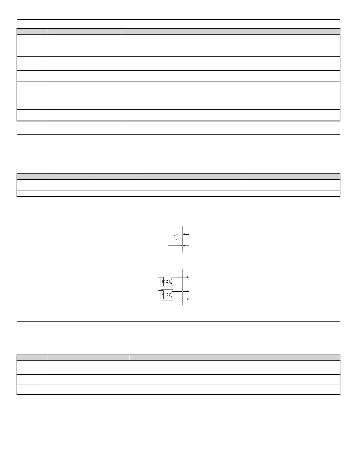
Multi-Function Contact Outputs
250 Vac, 10 mA - 1 A
30 Vdc, 10 mA - 1 A
(standard default setting)
Multi-Function Open-collector Outputs
48 Vdc, 50 mA or less
(standard default setting)
P1
P2
PC
During Run
Speed Agree
Open-collector Common
MA
MB
MC
Fault
Fault
(Open-collector 1)
(Open-collector 1)
Figure 4.25 Digital Output Connection Diagram
u
Analog Outputs: H4-01 to H4-03
Group U parameters can be used to observe the drive status (operating conditions) through the LED operator. Analog outputs corresponding to these
monitors can be obtained on analog output terminal AM or FM when programmed with parameter group H4. Some Group U monitors are not available
as analog outputs.
No. Parameter Name Description
H4-01
Multi-Function Analog 1 (Terminal AM Monitor
Selection)
Select the data to output through multi-function analog output terminal AM.
Set the desired monitor parameter to the digits available in Uo-oo. For example, enter “103” for U1-03.
When using this terminal as a through terminal or when not using it at all, set “000” or “031”.
H4-02 <1>
Multi-Function Analog 1 (Terminal AM Output
Gain)
Sets the voltage level gain of multi-function analog output 1 (terminal AM). The bias to be added ranges from 0 to +/- 10% when
10 V is assumed to be 100%.
H4-03 <1>
Multi-Function Analog 1 (Terminal AM Bias
Setting)
Sets the voltage level bias for terminal AM.
The bias added is 0 to ±10% with a maximum voltage output of 10 V as 100%.
<1> The parameter can be changed during run.
n
Changing Analog Output Settings
The following example illustrates how to program analog output terminal FM to generate a signal proportional to drive output current (monitor U1-03).
4.6 Basic Drive Setup Adjustments
86
YASKAWA ELECTRIC SIEP C710606 18A YASKAWA AC Drive – V1000 Technical Manual (Preliminary)

 Loading...


