No. Parameter Name Setting Range Default
H4-01 Multi-Function Analog 1 (Terminal AM Monitor Selection) 000 to 999 102
Note: If terminal AM is not used or is used as a through-put, then set H4-01 to 000 or 031.For information on available monitors and settings, U1: Status Monitors.
n
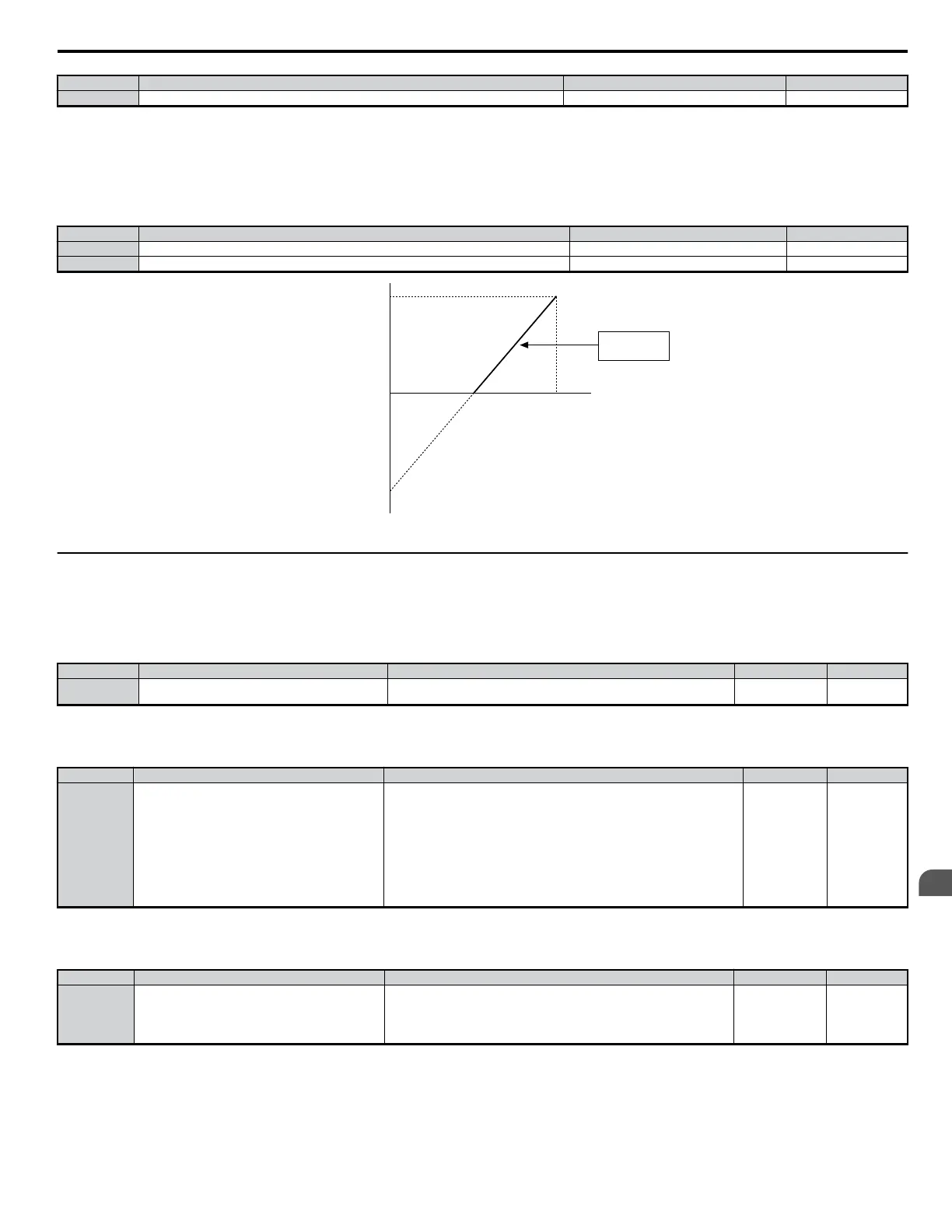
H4-02: Multi-Function Analog 1 (Terminal AM Output Gain)
n
H4-03: Multi-Function Analog 1 (Terminal AM Output Bias)
Sets the gain and bias of the voltage level output from terminal AM.
No. Parameter Name Setting Range Default
H4-02 Multi-Function Analog 1 (Terminal AM Output Gain) -999.9 to 999.9 100.0%
H4-03 Multi-Function Analog 1 (Terminal AM Output Bias) -999.9 to 999.9 0.0%
gain 100%
output voltage
bias -100%
0 V 5 V 10 V
Figure 5.67 Analog Output Gain/Bias Setting
u
H5: MEMOBUS/Modbus Serial Communication
Serial communication can be performed with programmable logic controllers (PLCs) or similar devices using the MEMOBUS/Modbus protocol.
n
H5-01: Drive Node Address
Parameter Overview
No. Name Description Range Default
H5-01 Drive Node Address
Selects drive station node number (address) for MEMOBUS/Modbus terminals
R+, R-, S+, S-. Cycle power for the setting to take effect.
0 to 20 H 1F
n
H5-02: Communication Speed Selection
Parameter Overview
No. Name Description Range Default
H5-02 Communication Speed Selection
Selects the baud rate for MEMOBUS/Modbus terminals R+, R-, S+ and S-. Cycle
power for the setting to take effect.
0 : 1200 bps
1 : 2400 bps
2 : 4800 bps
3 : 9600 bps
4 : 19200 bps
5 : 38400 bps
6 : 57600 bps
7 : 76800 bps
8 : 115200 bps
0 to 8 3
n
H5-03: Communication Parity Selection
Parameter Overview
No. Name Description Range Default
H5-03 Communication Parity Selection
Selects the communication parity for MEMOBUS/Modbus terminals R+, R-, S
+ and S-. Cycle power for the setting to take effect.
0: No parity
1: Even parity
2: Odd parity
0 to 2 0
n
H5-04: Stopping Method after Communication Error
Parameter Overview
5.7 H: Terminal Functions
YASKAWA ELECTRIC SIEP C710606 18A YASKAWA AC Drive – V1000 Technical Manual (Preliminary)
183
5
Parameter Details

 Loading...


