No. Description Setting Range Resolution
Control Modes (A1-02)
V/f (0) OLV (2) PM (5)
L3-21 Decel time at stall prevention during acceleration 0.00 to 200.00 0.01 1.00 1.00 2.50
<10> Default setting value is dependent on parameter E5-01, Motor Code Selection.
<12> Default setting value is dependent on parameter o2-04, Drive/kVA Selection.
<24> Values shown here are for 200 V class drives. Double the value when using a 400 V class drive.
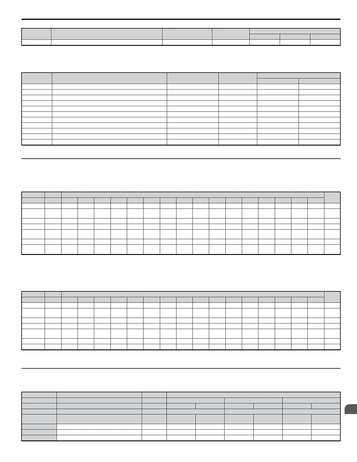
Table B.2 E3-01 (Motor 2 Control Mode) Dependent Parameters and Default Values
No. Description Setting Range Resolution
Control Modes (E3-01)
V/f (0) OLV (2)
E3-04 Maximum output frequency 40.0 to 400.0 0.1 Hz 60.0 60.0
E3-05 Maximum output voltage <24> 0.0 to 255.0 0.1 V 230.0 230.0
E3-06 Base Frequency 0.0 to 400.0 0.1Hz 60.0 60.0
E3-07 Middle output frequency 0.0 to 400.0 0.1Hz 3.0 3.0
E3-08 Middle output freq. voltage <24> 0.0 to 255.0 0.1 V 18.4 13.8
E3-09 Minimum output frequency 0.0 to 400.0 0.1 Hz 1.5 0.5
E3-10 Minimum output voltage <24> 0.0 to 255.0 0.1 V 13.8 2.9
E3-11 Middle output frequency 2 0.0 to 400.0 0.1 Hz 0.0 0.0
E3-12 Middle output freq. voltage 2 <24> 0.0 to 255.0 0.1 V 0.0 0.0
E3-13 Base voltage <24> 0.0 to 255.0 0.1 V 0.0 0.0
E3-14 Motor 2 Slip compensation gain 0.0 to 2.5 0.1 0.0 1.0
<24> Values shown here are for 200 V class drives. Double the value when using a 400 V class drive.
u
V/f Pattern Default Values
The tables below show the V/f pattern settings default values depending on the control mode (A1-02) and the V/f pattern selection (E1-03 in V/f control).
Table B.3 E1-03 V/f Pattern Settings for Drive Capacity: CIMR-VABA0001 to CIMR-VABA0010; CIMR-VA2A0001 to CIMR-VA2A0010; CIMR-VA4A0001 to CIMR-
VA4A0005
No. U V/f Control
OLV
E1-03 − 0 1 <55> 2 3 4 5 6 7 8 9 A B C D E F
E1-04 Hz 50.0 60.0 60.0 72.0 50.0 50.0 60.0 60.0 50.0 50.0 60.0 60.0 90.0 120 180 60.0 60.0
E1-05 <24>
V <61> 200 200 200 200 200 200 200 200 200 200 200 200 200 200 200 200 200
E1-06 Hz 50.0 60.0 50.0 60.0 50.0 50.0 60.0 60.0 50.0 50.0 60.0 60.0 60.0 60.0 60.0 60.0 60.0
E1-07 Hz 2.5 3.0 3.0 3.0 25.0 25.0 30.0 30.0 2.5 2.5 3.0 3.0 3.0 3.0 3.0 3.0 3.0
E1-08 <24>
V 16.0 16.0 16.0 16.0 35.0 50.0 35.0 50.0 19.0 24.0 19.0 24.0 16.0 16.0 16.0 16.0 12.0
E1-09 Hz 1.3 1.5 1.5 1.5 1.3 1.3 1.5 1.5 1.3 1.3 1.5 1.5 1.5 1.5 1.5 1.5 0.5
E1-10 <24>
V <61> 12.0 12.0 12.0 12.0 8.0 9.0 8.0 9.0 12.0 13.0 12.0 15.0 12.0 12.0 12.0 12.0 2.5
<24> Values shown here are for 200 V class drives. Double the value when using a 400 V class drive.
<55> Used as default settings for E1-04 to E1-10 and E2-04 to E2-10
<61> Multiply voltage values by 1.15 for U.S. models (CIMR-VU)
Table B.4 E1-03 V/f Pattern Settings for Drive Capacity: CIMR-VABA0012 to CIMR-
VABA0020;
CIMR-VA2A0012 to CIMR-VA2A0069; CIMR-VA4A0007 to CIMR-VA4A0038
No. U V/f Control
OLV
E1-03 − 0 1 <55> 2 3 4 5 6 7 8 9 A B C D E F
E1-04 Hz 50.0 60.0 60.0 72.0 50.0 50.0 60.0 60.0 50.0 50.0 60.0 60.0 90.0 120 180 60.0 60.0
E1-05 <24>
V 200 200 200 200 200 200 200 200 200 200 200 200 200 200 200 200 200
E1-06 Hz 50.0 60.0 50.0 60.0 50.0 50.0 60.0 60.0 50.0 50.0 60.0 60.0 60.0 60.0 60.0 60.0 60.0
E1-07 Hz 2.5 3.0 3.0 3.0 25.0 25.0 30.0 30.0 2.5 2.5 3.0 3.0 3.0 3.0 3.0 3.0 3.0
E1-08 <24>
V 14.0 14.0 14.0 14.0 35.0 50.0 35.0 50.0 18.0 23.0 18.0 23.0 14.0 14.0 14.0 14.0 11.0
E1-09 Hz 1.3 1.5 1.5 1.5 1.3 1.3 1.5 1.5 1.3 1.3 1.5 1.5 1.5 1.5 1.5 1.5 0.5
E1-10 <24> V 7.0 7.0 7.0 7.0 6.0 7.0 6.0 7.0 9.0 11.0 9.0 13.0 7.0 7.0 7.0 7.0 2.0
<24> Values shown here are for 200 V class drives. Double the value when using a 400 V class drive.
<55> Used as default settings for E1-04 to E1-10 and E2-04 to E2-10
u
Default Settings Determined by Drive Capacity (o2-04) and Normal / Heavy Duty Selection (C6-01)
Table B.5 Single-Phase, 200 V Class Drives
Default Settings by Drive Capacity and Normal/Heavy Duty Selection
No. Description Unit Default Settings
− Model CIMR-Vo − BA0001 BA0002 BA0003
C6-01 Normal/Heavy Duty Sel. Hex. HD ND HD ND HD ND
o2-04 kVA Selection − 30 31 32
E2-11 (E4-11,
T1-02)
Motor rated power kW 0.1 0.2 0.2 0.4 0.4 0.75
b3-06 Speed Search current 1 − 1 1 1 1 1 1
b8-04 Energy saving coefficient − 481.7 356.9 356.9 288.2 288.2 223.7
C6-02 Carrier frequency − 4 7 4 7 4 7
B.2 Parameter Table
YASKAWA ELECTRIC SIEP C710606 18A YASKAWA AC Drive – V1000 Technical Manual (Preliminary)
323
B
Parameter List

 Loading...


