4.3 The Drive and Programming Modes
The drive functions are divided into two main groups accessible via the Digital LED Operator:
Drive Mode: The Drive mode allows motor operation and parameter monitoring. Parameter settings cannot be changed when accessing functions in the
Drive Mode (
Table 4.2 ).
Programming Mode: The Programming Mode allows access to setup/adjust, verify parameters and Auto-Tuning. The drive prohibits changes in motor
operation such as start/stop when the Digital LED Operator is accessing a function in the Programming Mode.
Table 4.2 illustrates the different functions visible as the “Up arrow” is scrolled immediately after powering up the drive.
Note: When b1-08 (Run Command Selection while in Programming Mode) is set to 1 (enabled), the drive can run even if the mode is switched to the programming mode. When
setting b1-08 to 0 (disabled), the mode cannot be switched to the programming mode while the drive is running.
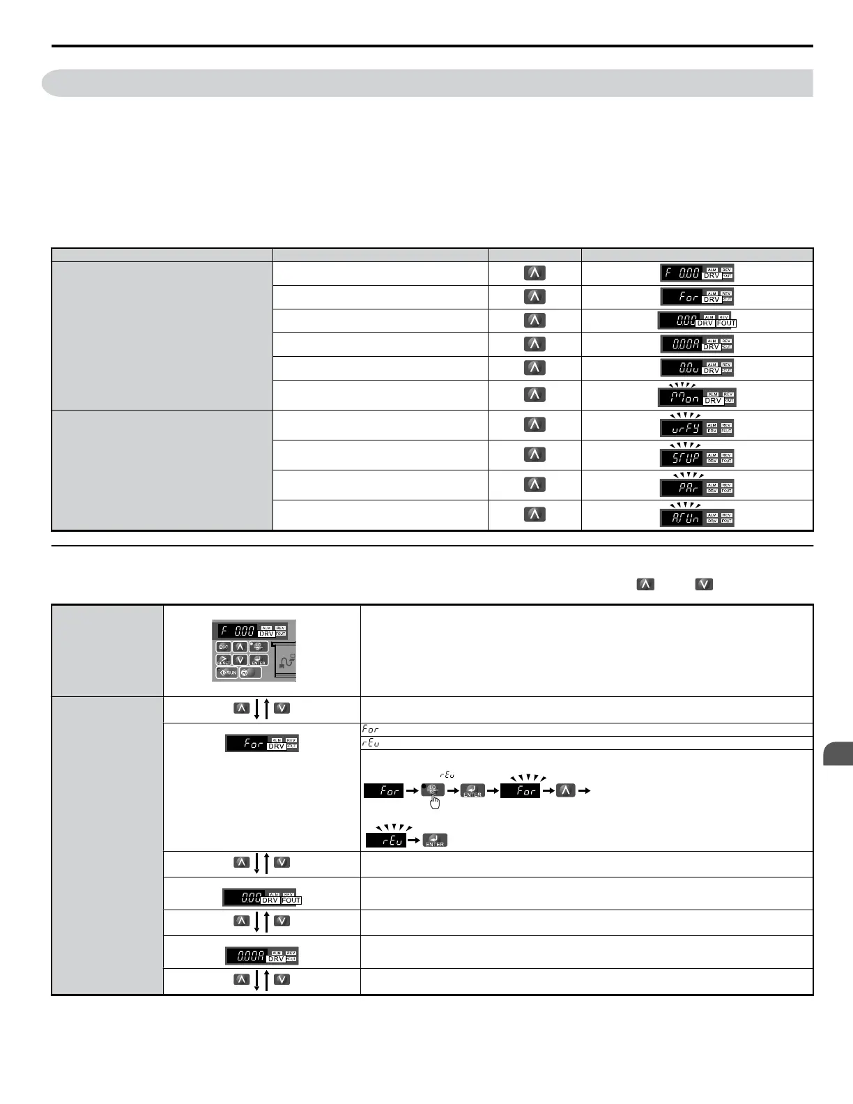
Table 4.3 Summary of Modes
Mode Group Description Key Press LED Digital Operator Display
Drive Mode Functions
(Motor operation and monitoring)
Frequency Reference Display (Initial power-up state)
Forward/Reverse
Output Frequency Display
Output Current Display
Output Voltage Reference
Monitor Display
Programming Mode Functions
(Changing parameters)
Verify Function
Setup Group Parameters
All Parameters
Auto-Tuning
u
Navigating the Drive and Programming Modes
The drive is set to operate in Drive Mode when it is first powered up. Switch between display screens by using the
and keys.
Power Up
Frequency Reference
Default Setting
This display screen allows the user to monitor and set the frequency reference while the drive is running. Refer to
The Drive and Programming Modes on page 61.
Note: The user can select items to display when the drive is first powered up by setting parameter o1-02.
Drive Mode
Forward/Reverse
: Motor rotates forward.
: Motor rotates in reverse.
Note: For applications that should not run in reverse (fans, pumps, etc.), set parameter b1-04 = “1” to prohibit the
motor from rotating in reverse. This sequence also puts the drive in LOCAL mode.
The LED is lit when
LOCAL is selected
Switching to reverse:
Output Frequency Display
Monitors the frequency output by the drive.
Output Current Display
Monitors the output current of the drive.
4.3 The Drive and Programming Modes
YASKAWA ELECTRIC SIEP C710606 18A YASKAWA AC Drive – V1000 Technical Manual (Preliminary)
61
4
Start-Up Programming
& Operation

 Loading...


