C.5 Command/Response Message Format
Below are some examples of command and response messages.
u
Reading Drive Memory Register Contents
The contents of the memory register are separated into higher 8 bits and lower 8 bits. A maximum of 16 drive memory registers can be read out at a time.
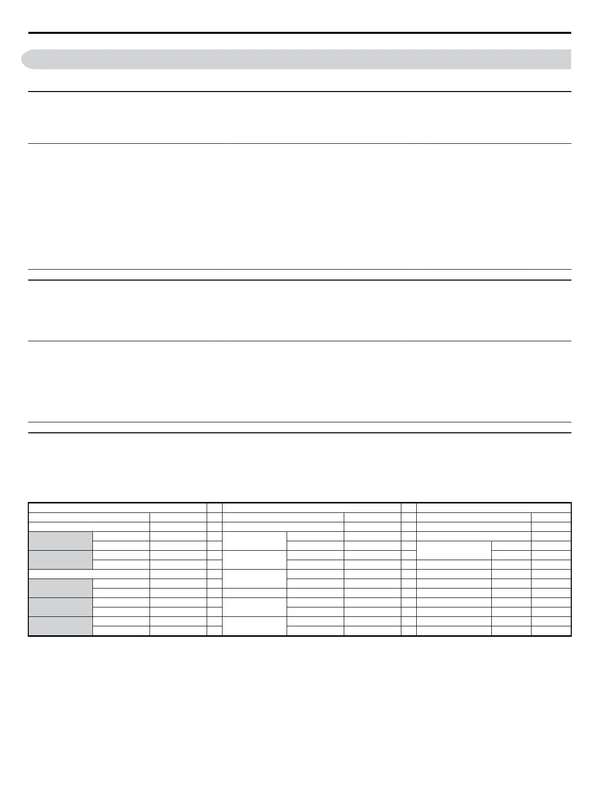
The following table shows message examples when reading status signals, error details, data link status, and frequency references from the slave 2 drive.
Command Message
Response Message (normal) Response Message (fault)
Slave Address 02H Slave Address 02H Slave Address 02H
Function Code 03H Function Code 03H Function Code 83H
Starting No.
Upper 00H Data Quantity 08H Error Code 03H
Lower 20H
1st storage register
Upper 00H
CRC-16
Upper F1H
Quantity
Upper 00H Lower 65H Lower 31H
Lower 04H
Next storage register
Upper 00H
CRC-16
Upper 45H Lower 00H
Lower F0H
Next storage register
Upper 00H
Lower 00H
Next storage register
Upper 01H
Lower F4H
CRC-16
Upper AFH
Lower 82H
u
Loop Back Test
The loopback test returns command messages directly as response messages without changing the contents to check the communications between the
master and slave. User-defined test code and data values can be set.
The following table shows a message example when performing a loop back test with the slave 1 drive.
Command Message
Response Message (normal) Response Message (fault)
Slave Address 01H Slave Address 01H Slave Address 01H
Function Code 08H Function Code 08H Function Code 89H
Test Code
Upper 00H
Test Code
Upper 00H Error Code 01H
Lower 00H Lower 00H
CRC-16
Upper 86H
Data
Upper A5H
Data
Upper A5H Lower 50H
Lower 37H Lower 37H
CRC-16
Upper DAH
CRC-16
Upper DAH
Lower 8DH Lower 8DH
u
Writing to Multiple Registers
The writing of drive memory registers works similar to the reading process, i.e., the address of the first register that is to be written and the quantity of to
be written registers must be set in the command message. The data to be written must be consecutive, starting from the specified address in the command
message. The data order must be higher 8 bits, then lower 8 bits. The data must be in memory register address order.
The following table shows an example of a message where a forward operation has been set with a frequency reference of 60.0 Hz for the slave 1 drive.
Command Message
Response Message (normal) Response Message (fault)
Slave Address 01H Slave Address 01H Slave Address 01H
Function Code 10H Function Code 10H Function Code 90H
Starting No.
Upper 00H
Starting No.
Upper 00H Error Code 02H
Lower 01H Lower 01H
CRC-16
Upper CDH
Quantity
Upper 00H
Quantity
Upper 00H Lower C1H
Lower 02H Lower 02H
Data Quantity 04H
CRC-16
Upper 10H
Starting Data
Upper 00H Lower 08H
Lower 01H
Next Data
Upper 02H
Lower 58H
CRC-16
Upper 63H
Lower 39H
Note: For the number of data value in the command message, take double the number of the data value.
C.5 Command/Response Message Format
336
YASKAWA ELECTRIC SIEP C710606 18A YASKAWA AC Drive – V1000 Technical Manual (Preliminary)

 Loading...


