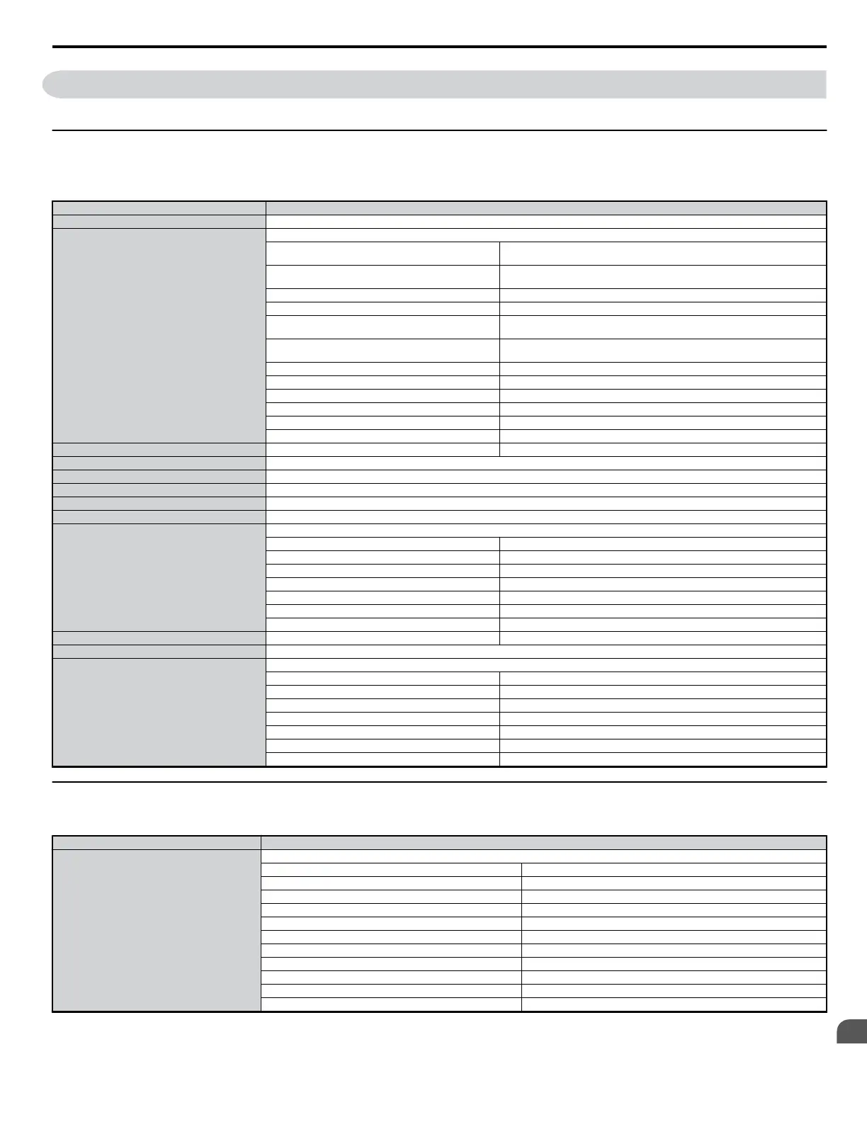
C.6 MEMOBUS/Modbus Data Table
Table below lists all MEMOBUS/Modbus data. There are three types of data: command data, monitor data, and broadcast data.
u
Command Data
It is possible to both read and write command data.
Note: Bits that are not used should be written as 0. Refrain from writing to reserved registers.
Register No. Contents
0000H Reserved
0001H
Operation Signals
bit 0
H5-12 = 0: Forward Run Command (0 = Stop, 1 = Run) H5-12 = 1: Run Command
(0 = Stop, 1 = Forward Run)
bit 1
H5-12 = 0: Reverse Run Command (0 = Stop, 1 = Run) H5-12 = 1: Forward/Reverse
(0 = Stop, 1 = Reverse Run)
bit 2 External Fault (EF0)
bit 3 Fault Reset
bit 4
Multi-Function Input Command 1 ComRef when set for Forward/Stop Note: If
H1-01 = 40, then bit 4 becomes ComRef.
bit 5
Multi-Function Input Command 2 ComCtrl when set for Reverse/Stop Note: If
H1-02 = 42, then bit 5 becomes ComCtrl.
bit 6 Multi-Function Input 3
bit 7 Multi-Function Input 4
bit 8 Multi-Function Input 5
bit 9 Multi-Function Input 6
bit A Multi-Function Input 7
bit B to bit F Reserved
0002H Frequency Reference Varies by the setting units set to o1-03.
0003H V/f Gain
0004H-0005H Reserved
0006H PID Target (0.01% signed)
0007H Analog Output 1 setting (10 V / 4000 H)
0008H Analog Output 2 setting (10 V / 4000 H)
0009H
Settings for Multi-Function Digital Outputs
bit 0 Contact Output (terminal MA/MB-MC)
bit 1 Photocoupler Output 1 (terminal P1-PC)
bit 2 Photocoupler Output 2 (terminal P2-PC)
bit 3 to bit 5 Reserved
bit 6 Fault Contact Output Enabled (1 = enabled by bit 7)
bit 7 Fault contact (terminal MA/MB-MC)
bit 8 to bit F Reserved
000AH PO Output 1/1 Hz Setting Range: 0 to 32000
000BH-000EH Reserved
000FH
Control Selection Setting
bit 0 Reserved
bit 1 PID Target Input
bit 2 to bit B Reserved
bit C Broadcast Data Terminal S5 Input
bit D Broadcast Data Terminal S6 Input
bit E Broadcast Data Terminal S7 Input
bit F Reserved
u
Monitor Data
Monitor data is read only.
Register No. Contents
0020H
Drive Status
bit 0 During Run
bit 1 During Reverse
bit 2 Drive Ready
bit 3 Fault
bit 4 Data Setting Error
bit 5 Multi-Function Contact Output (terminal MA/MB-MC)
bit 6 Multi-Function Photocoupler Output 1 (terminal P1 - PC)
bit 7 Multi-Function Photocoupler Output 2 (terminal P2 - PC)
bit 8 to bit D Reserved
bit E ComRef status
bit F ComCtrl status
C.6 MEMOBUS/Modbus Data Table
YASKAWA ELECTRIC SIEP C710606 18A YASKAWA AC Drive – V1000 Technical Manual (Preliminary)
337
C
MEMOBUS/Modbus
Communications

 Loading...


