Note the following when using the Multi-Step Speed function:
• As shown in the table above, it is possible to use analog inputs in place of Frequency Reference 1 and 2.
• If b1-01 = 1, then the analog input A1 will be used instead of Frequency Reference 1 (d1-01) for the first preset speed.
• If b1-01 = 0 then Frequency Reference 1 (d1-01) will be used.
• When H3-10 = 2, then the value input to terminal A2 will be used as the Multi-Step Speed 2 instead of the value set to parameter d1-02. When H3-10
does not equal 2, then d1-02 becomes the reference for Multi-Step Speed 2.
d1-04
20.0 Hz
d1-01
5.0Hz
d1-02
10.0 Hz
d1-03
15.0 Hz
d1-05
25.0 Hz
d1-06
30.0 Hz
d1-07
35.0 Hz
d1-17
6.0Hz
d1-12
60.0 Hz
d1-13
65.0 Hz
d1-14
70.0 Hz
d1-15
75.0 Hz
d1-16
80.0 Hz
ON
ON
ON
ON
ON
ON
ON
ON
ON
ON
ON
ON
ON
ON
ON
FWD (REV) Run/Stop
Multi-step Speed Ref. 2
Term.S4
Multi-step Speed Ref. 3
Term.S5
Jog Ref.
Term.S7
Time
Multi-step Speed Ref. 1
Term.S3
Multi-step Speed Ref. 4
Term.S6
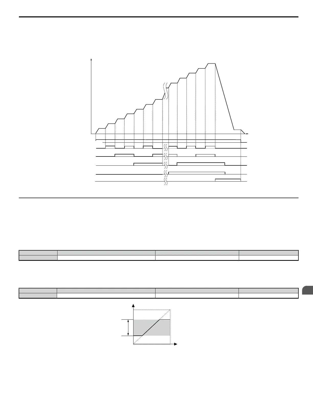
Frequency Reference
Figure 5.31 Preset Reference Timing Diagram
u
d2: Frequency Upper/Lower Limits
By entering upper or lower frequency limits, the drive programmer can prevent operation of the Drive above or below levels that may cause resonance
and or equipment damage.
n
d2-01: Frequency Reference Upper Limit
Sets the highest frequency that the motor is able to rotate at. This limit applies to all frequency references.
Parameter d2-01 is set as a percentage of the maximum output frequency. Even if the frequency reference is set to a higher value, the drive internal
frequency reference will not exceed this value.
No. Parameter Name Setting Range Default
d2-01 Frequency Reference Upper Limit 0.0 to 110.0 100.0%
n
d2-02: Frequency Reference Lower Limit
Sets the lowest frequency that the motor is able to rotate at. This limit applies to all frequency references.
Determines the minimum frequency that the drive can output as a percentage of the maximum output frequency.
No. Parameter Name Setting Range Default
d2-02 Frequency Reference Lower Limit 0.0 to 110.0 0.0%
Internal Speed Command
d2-01
Operating
Range
Frequency Reference Upper Limit
Set Speed Command
Frequency Reference Lower Limit
d2-02
Figure 5.32 Frequency Reference: Upper and Lower Limits
5.4 d: Reference Settings
YASKAWA ELECTRIC SIEP C710606 18A YASKAWA AC Drive – V1000 Technical Manual (Preliminary)
141
5
Parameter Details

 Loading...


