n
d1-17: Jog Frequency Reference
Up to 17 preset references (including Jog Reference) can be set through multi-function inputs S3 to S8.
No. Parameter Name Setting Range Default
d1-01 to d1-16 Frequency Reference 1 to 16
0.00 to 400.00
*
0.00 Hz
d1-17 Jog Frequency Reference
0.00 to 400.00
*
6.00 Hz
Note: The upper limit is determined by the maximum outupt frequency (E1-04) and upper limit for the frequency reference (d2-01).
Detailed Description
To set up 17 separate steps for the speed reference, assign Multi-Step Speed functions to H1-01 to H1-07 (these parameters control the functions set to
terminals S1 to S7).
Note: Terminal S5 needs to be set for Multi-Step Speed 1 (H1-05 = 3), and terminal S6 needs to be set for Multi-Speed Step 2 (H1-06 = 4). To have the drive accelerate as shown
in the Multi-Step Speed operation shown in this section, parameters need to be changed from their default values as described. Because the Jog Frequency is already assigned
to terminal S7 as a default (H1-07 = 6), this setting does not need to be changed.
The drive is defaulted for a 2-step speed operation via the analog input terminals. To enable Multi-Step Speed 1 and 2, set the drive as shown below.
No. Parameter Name Setting Range Default Page
b1-01 Frequency Reference Selection 0 to 4 1 −
H3-10 Terminal A2 Function Selection 0 to 31 0 −
Procedure
Follow the directions below to set the drive up for Multi-Step Speed operation (allows 17 steps). The example assumes the drive is operating in REMOTE
mode using an analog signal.
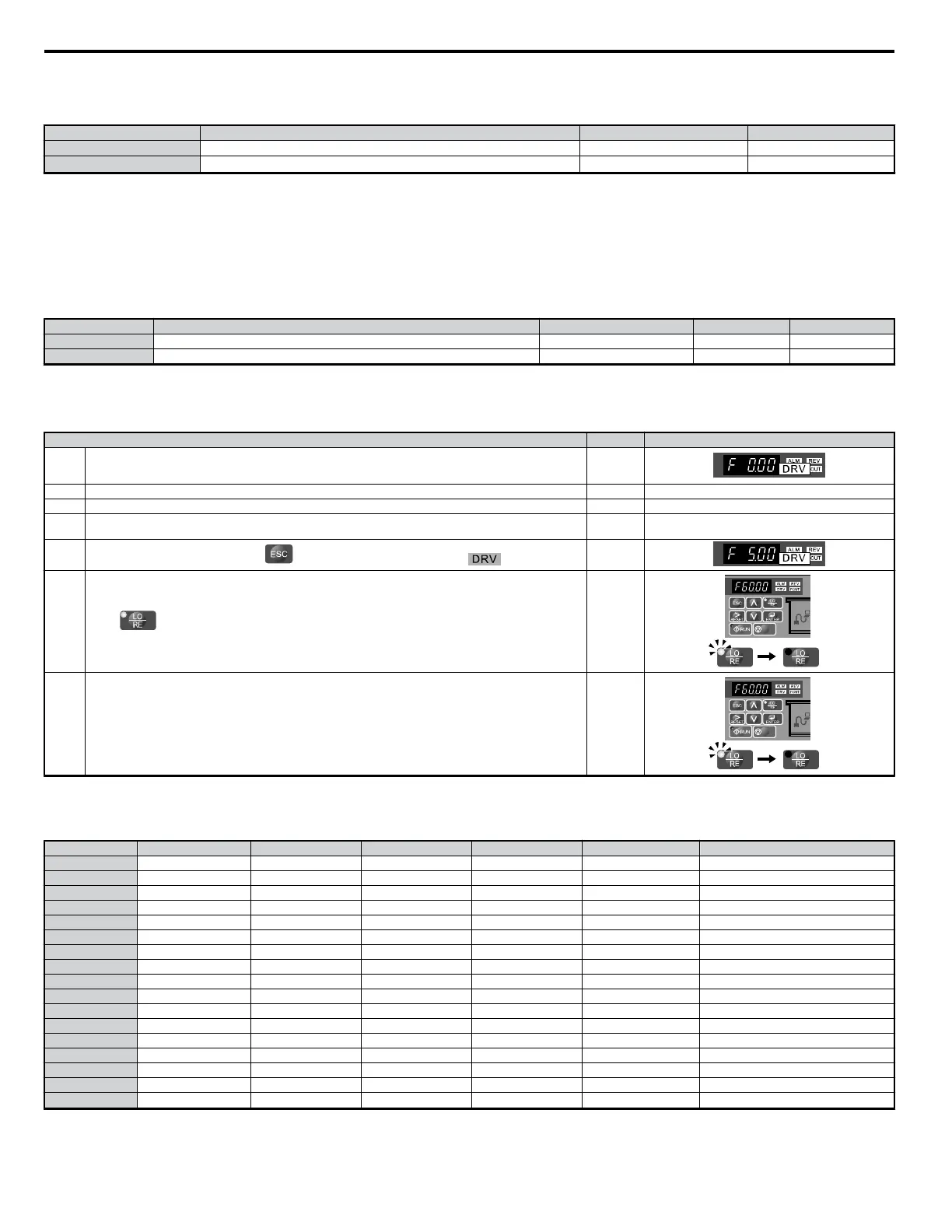
Step Display/Result
1.
Power up the drive. Assign the source of the frequency reference to the LED operator (b1-02 = 1). The run command
should already be defaulted to the control circuit terminal (b1-02 = 1). Set multi-function analog input terminal A2
to “Not Used” (H3-10 = F).
⇒
2. Set the desired frequencies to d1-01 through d1-16.
3. Set the desired Jog Frequency value to d1-17.
4.
Set multi-function input terminals S3 through S6 for Multi-Step Speed 1 to 4 (H1-03 = 3, H1-04 = 4, H1-05 = 5,
H1-06 = 32).
5.
After setting frequency refrences, press to scroll back to the main screen. The LED should light.
⇒
6.
Press to select REMOTE. The LO/RE light will come on.
⇒
7.
The drive will run the motor at the frequencies set to parameters d1-01 through d1-17, selecting each frequency
reference according to the switching combination of multi-function input terminals S3 through S7. This allows for
17 separate speed steps (including the Jog Frequency).
⇒
Different frequency references can be given to the drive through various switching combinations of multi-function input terminals S3 through S7. Below
is a list of the possible combinations.
Table 5.3 Multi-Step Speed Reference and Terminal Switch Combinations
d1-01 to d1-17 Multi-StepSpeed Multi-StepSpeed 2 Multi-StepSpeed 3 Multi-StepSpeed 4 Jog Reference Reference
1 OFF OFF OFF OFF OFF Frequency Reference 1 (d1-01)
2 ON OFF OFF OFF OFF Frequency Reference 2 (d1-02)
3 OFF ON OFF OFF OFF Frequency Reference 3 (d1-03)
4 ON ON OFF OFF OFF Frequency Reference 4 (d1-04)
5 OFF OFF ON OFF OFF Frequency Reference 5 (d1-05)
6 ON OFF ON OFF OFF Frequency Reference 6 (d1-06)
7 OFF ON ON OFF OFF Frequency Reference 7 (d1-07)
8 ON ON ON OFF OFF Frequency Reference 8 (d1-08)
9 OFF OFF OFF ON OFF Frequency Reference 9 (d1-09)
10 ON OFF OFF ON OFF Frequency Reference 10 (d1-10)
11 OFF ON OFF ON OFF Frequency Reference 11 (d1-11)
12 ON ON OFF ON OFF Frequency Reference 12 (d1-12)
13 OFF OFF ON ON OFF Frequency Reference 13 (d1-13)
14 ON OFF ON ON OFF Frequency Reference 14 (d1-14)
15 OFF ON ON ON OFF Frequency Reference 15 (d1-15)
16 ON ON ON ON OFF Frequency Reference 16 (d1-16)
17 Jog − − − − ON
Jog Frequency Reference (d1-17)
*
*The Jog Frequency overrides whatever frequency reference is being used.
5.4 d: Reference Settings
140
YASKAWA ELECTRIC SIEP C710606 18A YASKAWA AC Drive – V1000 Technical Manual (Preliminary)

 Loading...


